Harmony Series 2 Homelift - XH00200 Issue: D Page 72 of 106
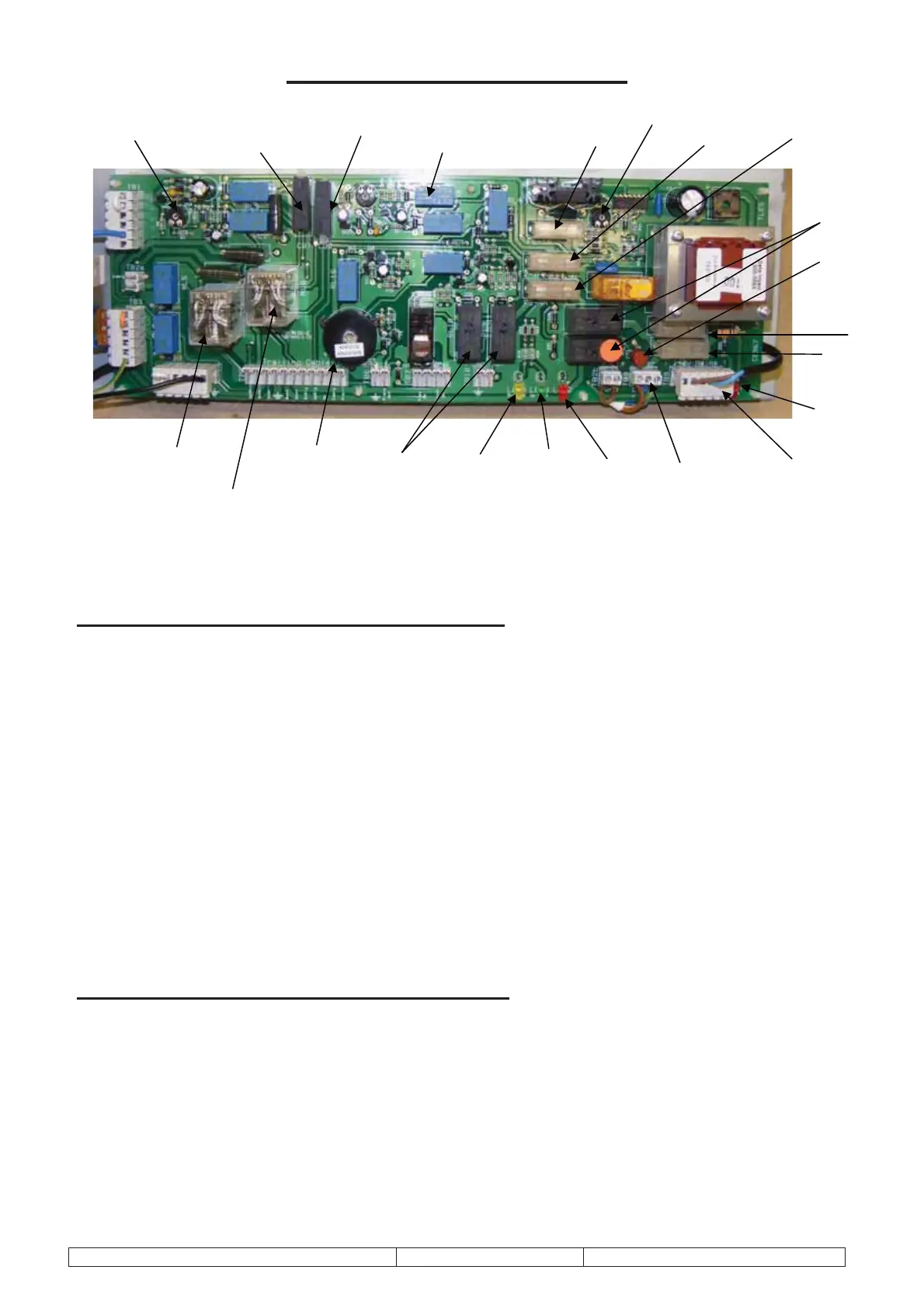
Main Controller PCB (CE966)
Function of fuses on Main controller PCB
FUSE Fuse ratingType of circuit protected
F1 -
10 Amps - Mains feed to the pump
F2 -
2 Amps - This fuse protects the up and down controlrelays (RL7 and RL8) and
the delay and run circuit.
F3 -
4 Amps - 12V Feed to power pack solenoid will blow if final limit is operated
and down signal applied.
F4 -
500 mA - Mains feed to transformer providing charger voltage output on TB5
Batt output
F5 -
Not Required - Onboard Charger Disabled
F6 -
160mA - Anti-weld circuit (isloate) from mains cross feed
CB1 -
1 Amp - Blows if run time is exceeded (up direction only)
CB2 -
2 Amps - Feed emergency circuit – will blow when up or down signal is given
and the safety circuit board is detecting a fault.
Function of LED’s on Main controller PCB
LED 1 (RED) ON = Mains supply OK
LED 2 (RED) ON = Onboard charger enabled and is used to indicate mains voltage is
present on the CE966 PCB.
LED 3 (GREEN) Up weld indicator - ON when mains off, F6 is blown or when 1 or both up
final relays (RLY 11 and 12) have welded contacts.
LED 4 (YELLOW) Down weld indicator – ON when fuse F3 (pump solenoid) has blown
(maybe final limit operated). Or when 1 or both down final relays (RL9
and 10) have welded contacts.
F6
ALARM
SOUNDER
CHARGER (SET TO 13.65V)
DELAY TIMER
FINAL UP
RELAYS
(RL11 & 12)
UP
WELD
LED 3
DOWN
WELD
LED 4
FINAL
DOWN
RELAYS
(RL9 & 10)
CB1
CB2
RUN TIMER
(FULLY ANTI-CLOCKWISE)
UP
CONTROL
RELAY
DOWN
CONTROL
RELAY
PUMP
MOTOR
OUTPUT
MAINS
INPUT
F4
F1
F3
F2 F5
CHARGER
LED 2
MAINS
INPUT
LED 1



 To Next Page