Harmony Series 2 Homelift - XH00200 Issue: D Page 44 of 106
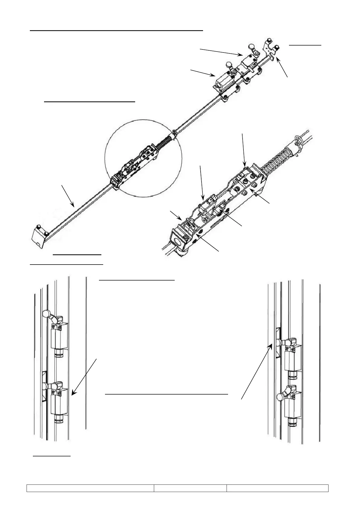
Which Switches Do What?
UPPER DOOR ENABLE
LOWER DOOR ENABLE & U/PAN O’RIDE
BRACKETS
– at each end of pole for
mounting to sling
FINAL LIMIT SWITCH
FINAL LIMIT SAFETY SWITCH
POLE FABN.
– for mounting control
mechanism/switches
CREEP LATCH SWITCH
DUMP SWITCH
CREEP SWITCH
TOP LIMIT SWITCH
TOP END
BOTTOM END
Car/Sling Switch Settings and Adjustments
Zone Switch Settings
When Lift is Downstairs
The second switch from the top of the control
mechanism (lower door enable and u/pan
o’ride) should be adjusted so that its roller level
is horizontal, positioned at the centre of the cut
out in the control tube as shown.
As the car descends this switch should close no
earlier than 8mm before the underpan touches
the floor and no later than 4mm. Adjustment
can be made by moving the safe edge override
switch up or down.
When Lift is Upstairs at Finished Level
The top switch of the control mechanism
(upper door enable) should be adjusted so
that its roller lever is horizontal, positioned
at the centre of the cut out in the control
tube as shown.
IMPORTANT! – All switches on the control mechanism must be pushed as close to the control tube
as possible, on the slots provided.



 To Next Page