Harmony Series 2 Homelift - XH00200 Issue: D Page 54 of 106
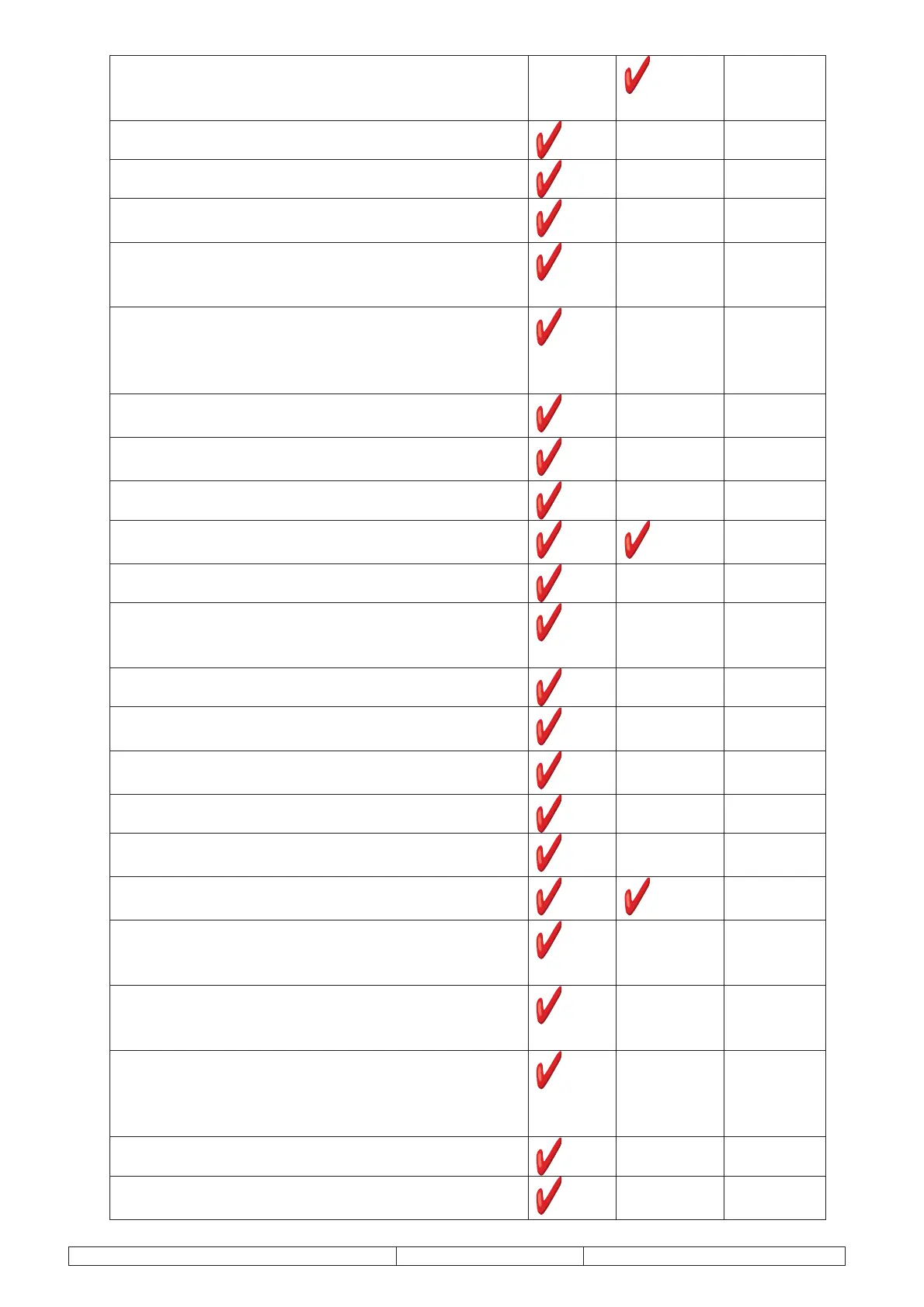
Lower the trapdoor leg into position / Fit
Rectangular washers. Final adjustment required
later.
Fit Bearing on trapdoor leg.
Fit red rod and guide bracket on top of sling.
Pull wires from switch assembly up in to the top
half of the sling along with trailing cables 1 and 2
Assemble the Carriage using shims on Tilting
floor fixings and attach to the sling doing
packing and spacing as normal.
Before the door is fitted, do the on-site load
test. Check that the pressure switch is set at
55 bar. Perform test and record result in test
certificate.
If lift has a LW Car, change pressure switch
setting to 60 bar, after on-site load test.
Fit the top safe edge assemblies and connect
wires
Fit the door and connect door cables up.
Power the lift up and fit the under pan and
profile trim.
Adjust the ram plates.
Lower the lift manually and tilt the floor if
necessary. (May need to adjust Ram plates
again)
Set the Underpan switch assemblies x 4.
Fit the sling PCB assembly (Bolt with earth on
LHS and Velcro RHS).
Fit the 2 batteries and ensure that all wires are
clipped to the rear of the sling PCB Panel.
Connect all wiring to sling PCB and tidy looms.
Set auxiliary voltage charger to 13.7V using VR3
on the CE966 PCB.
Power the lift up checking for any snagging
wires etc.
With the trapdoor picked up, adjust the trapdoor
arm with the carpet or hammer on top so the
arm is level.
Line up the trapdoor infill panel inside the
aperture using the 4 x M8 nuts on the top of the
panel
Pick the trapdoor up and adjust the creep block
so the red rod is 3mm below the plunger on the
trapdoor. DO NOT over tighten top fixing in
creep assembly.
Adjust the 2 trapdoor switches.
Set the trapdoor override switch (20mm pad)
using the bottom roller switch with white roller


 To Next Page