Powerwall must be installed by a Tesla Energy Certified Installer.
STEP 1 - REMOVE THE PALLET
STEP 2 - DETERMINE THE MOUNTING LOCATION FOR POWERWALL
STEP 3 - INSTALL THE WALL MOUNT BRACKET
STEP 4 - MOUNT POWERWALL
STEP 5 - REMOVE THE PACKAGING
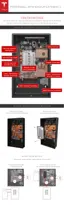
STEP 6 - REMOVE THE BOTTOM COVER
STEP 7 - REMOVE THE SPLASH COVER
STEP 8 - SET THE CONFIGURATION SWITCHES
STEP 9 - SET THE ADDRESS SWITCHES
STEP 10 - PREPARE THE WIRING
STEP 11 - FEED WIRES THROUGH THE CONDUIT PLATE OR CABLE GLAND
STEP 12 - CONNECT THE WIRING
STEP 13 - CONNECT MULTIPLE POWERWALLS TOGETHER
STEP 14 - CONNECT POWERWALL TO THE INVERTER
STEP 15 - ATTACH THE SIDE COVERS
STEP 16 - ATTACH THE SPLASH COVER
STEP 17 - ATTACH THE BOTTOM COVER
STEP 18 - REPACK THE SHIPPING BOX
REQUIRED TOOLS
• Wall mount bracket fasteners
Note: The details below are only guidance and are not guaranteed to be applicable. Consult
local building codes and a structural engineer to ensure the use of appropriate fasteners.
• Minimum of 6 fasteners, stainless steel, diameter 10 mm (3/8 in)
• Fastener head clearance for all positions but two bottom outer holes: 18 mm (11/16 in)
• Fastener head clearance for bottom two holes at 600 mm (24 in) spacing: 8 mm (5/16 in)
• Washers between fastener heads and wall mount bracket are recommended
• Drill and a drill bit suitable for drilling pilot holes in the desired mounting surface
• Socket wrench
• 10 mm socket adapter (for covers and wall mount bracket side tabs)
• 17 mm socket adapter (for wood block bolts)
• Large
flathead screwdriver (for ground lug)
• Optional: small flathead screwdriver (for wiring terminal tabs)
• T20 Torx (for splash cover)
• T25 Torx (for screws fastening box to wood blocks)
• T30 Torx (for packaging L-bracket and conduit/gland plate)
• Torque wrench
• Stud
finder (for wood installations)
• Level tool
• Painter's tape and/or pencil
• Wire stripper and wiring (as described in Step 10)
• Conduit
fitting or cable gland (as appropriate)
• Lift tool or adequate personnel trained and capable of lifting 115 kg (254 lb) from ground level
to approximately chest height
Warning: Powerwall is heavy and challenging to lift. Lift equipment is recommended.
To prevent injury, wear work boots (preferably steel-toed), long pants, and gloves.
Step-by-Step Installation Instructions
Step-by-Step Installation Instructions 9