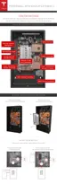
STEP 9 - SET THE ADDRESS SWITCHES
DIP switches are located closer to the thermal power connectors. This block has three white pins
numbered “1”, “2”, and “3” from top to bottom with a value of ‘1’ to the left and ‘0’ to the right.
These switches are used to oset the address from 0 through 7.
• Over Modbus, the base address is 0x18 (24). This is added to the DIP switch settings for the
overall Powerwall address, with values between 0x18 and 0x1F (24-31).
• Over CAN, the base address is 0x50 (80). This is added to the DIP switch settings for the
overall Powerwall address, with values between 0x50 and 0x57 (80-87).
Set the switches according to Powerwall position. In a multi-Powerwall configuration, use the DIP
switches to select contiguous and discrete osets from 0 through 7 (with 0 as the first Powerwall,
1 as the second Powerwall, continuing to 7 as the last Powerwall).
Set a single Powerwall using Powerwall 0 settings.
Switch
Number
PW 0 PW 1 PW 2 PW 3 PW 4 PW 5 PW 6 PW 7
1 Right Left Right Left Right Left Right Left
2 Right Right Left Left Right Right Left Left
3 Right Right Right Right Left Left Left Left
Step-by-Step Installation Instructions
Step-by-Step Installation Instructions 19