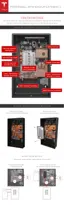
At this point, all wires should be connected, leaving the communication port (J6) on the left
unused. Ensure that all wires are routed around the existing cables and towards the top left of the
circuit board (at the front of Powerwall).
If installing multiple Powerwalls, communication wires can be daisy-chained as described in the
next section.
Verify that the polarities of all power and communication cables are correct.
STEP 13 - CONNECT MULTIPLE POWERWALLS TOGETHER
If the site is installing multiple Powerwalls, follow these instructions for wiring the units.
Note: Ensure that the multi-Powerwall installation meets local requirements for DC disconnects
and correctly rated overcurrent protection.
Note: Always check with the inverter partner for inverter abilities and instructions before
connecting multiple Powerwalls.
1. Connect the wiring coming from the inverter (communications +/-, enable line, and 12V Logic
+/- wires) to the J7 connector as the primary connector.
2. Connect the output communications, enable, and 12V logic wiring going toward the next
Powerwall to the J6 connector.
3. Run 12V thermal power independently to each Powerwall. Depending on the 12V power
capability of the inverter, and the use case (running two Powerwalls simultaneously vs. in
series), it may be necessary to add additional 12V power supplies. If the inverter’s 12V power
supply can support multiple Powerwalls, it is possible to splice multiple 12V runs together.
Caution: Do not splice 12V wiring inside Powerwall.
4. Run high voltage wiring independently to each Powerwall.
STEP 14 - CONNECT POWERWALL TO THE INVERTER
Run the wires between Powerwall and the inverter as described in the inverter manual. Follow
local electrical installation codes for wire installation.
Note: Ensure that the installation meets local requirements for DC disconnects and correctly rated
overcurrent protection.
Step-by-Step Installation Instructions
24