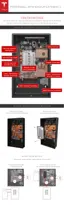
STEP 10 - PREPARE THE WIRING
Refer to local building and electrical codes when selecting appropriate wire gauge and length. Cut
the ends of the wires to have clean, even ends. Strip the ends of the wires enough to make solid
contact in the connector, while ensuring that no bare wire extends beyond the connector edge.
Depending on the configuration of the inverter, a single 12 V power connection to the 12V TH
header can supply power to the logic, the pump, and the fan. If the inverter has two 12 V
connections, be sure to match the connection correctly within the system. The Logic 12 V might
be called "Logic," "Always On," "Communication," or similar. The Thermal 12 V might be called
"Thermal," Switched," "Pump/Fan," "Cooling," or similar.
Caution: Do not splice 12 V wiring inside Powerwall.
Caution: Do not add extra wiring to the left of the conduit or gland entry. Additional wiring
may interfere with water and high voltage shielding to the pump.
Note: Use shielded communication wire and ground the shielding at one end. This reduces the
possibility of noise on the communication cable. Do not ground the shield at both ends, which
would create a ground loop.
The 450 VDC cable is run in close proximity to the communication cabling. Therefore, ensure that
all cables to Powerwall are at least 600 V insulation class and are wet or oil rated.
Step-by-Step Installation Instructions
20