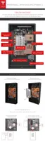
STEP 16 - ATTACH THE SPLASH COVER
1. Align the splash cover with the circuit board.
2. Route the wires upward (away from the wall) to keep them away from the Enable button.
When the splash cover is removed, the Enable button disables power to the unit for service.
Warning: Misrouted wiring that keeps the button pressed in when the cover is o can
create a risk of electric shock. Ensure the Enable button is not pressed by any wiring.
3. Ensure that all wires route out of the splash cover through its opening, and that wires are not
pinched or kinked.
4. Ensure that the Enable button is pressed when the cover is attached. Listen for the click of the
button being pressed.
5. Use a T20 Torx driver to attach the splash cover with two M4 screws. Torque to 3 Nm (27 in-
lbs).
STEP 17 - ATTACH THE BOTTOM COVER
1. Line up the bottom cover with the bottom of Powerwall, between the side covers.
2. Tuck the back edge of the bottom cover (closest to the wall) under the metal edge of the
Powerwall body.
3. Route the wires to run from the conduit plate or gland back (toward the wall) below the
ground lug, then forward again to match the internal wiring harness path under the splash
cover into the circuit board. Verify that the wires are not pinched or kinked by the internal
edge of the bottom cover.
4. Close the bottom cover carefully over the wiring. Verify that the edge of the bottom cover is
tucked completely under the lip of the front cover.
5. Use a 10 mm hex socket to attach the bottom cover with an M6 screw on each side. Torque to
3 Nm (27 in-lbs).
6. Once installation is complete, gently peel the protective sticker from Powerwall's front cover.
STEP 18 - REPACK THE SHIPPING BOX
All Powerwall packing material is recyclable. To facilitate this process, place the packing materials
into the shipping box in reverse order and return the shipping box to the Tesla Energy Authorized
Reseller, or recycle onsite as appropriate.
Step-by-Step Installation Instructions
26