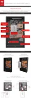
STEP 7 - REMOVE THE SPLASH COVER
Note: When the splash cover is removed, an Enable circuit disables the internal electronics of
Powerwall. The Enable button is located at the bottom of the circuit board, near the HV power
connectors.
Warning: Ensure the Enable button is not pressed by any wiring.
Warning: The Enable button only disables power from Powerwall. It does not disable power
from the inverter.
1. Turn o power to the relevant areas of the building at the circuit breaker panel.
2. Turn o the inverter.
3. Open the DC disconnect switch (if applicable for the installation).
4. Use a multimeter to verify that the wires from the inverter to Powerwall are not live.
5. Use a T20 Torx driver to remove the two splash cover screws.
6. Carefully remove the splash cover. Ensure that nothing is caught or bent. Set the screws and
cover aside for reassembly after the wiring is complete.
Warning: Use a multimeter to ensure no voltage is present on the terminals of the Powerwall
circuit board.
Step-by-Step Installation Instructions
Step-by-Step Installation Instructions 17