Installation
17
Switch position
The respective switch position is read after evaluating a measuring
result and after a reset.
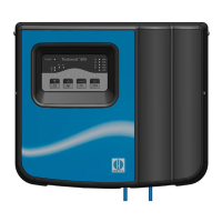
Slide switch T1
Switch position LEFT: If the slide switch is in the left position
and the instrument is switched on or the reset key pressed while the
instrument is switched on, the microcontroller executes the operating
program (firmware).
Switch position RIGHT: If the slide switch is in the right position
and the instrument is switched on or the reset key pressed while the
instrument is switched on, the instrument is set to a mode which ena-
bles a firmware update via the serial interface.
If your instrument requires a firmware update, Heyl will provide you
with further detailed information.
Switch position
The switch position is only read immediately after a reset.
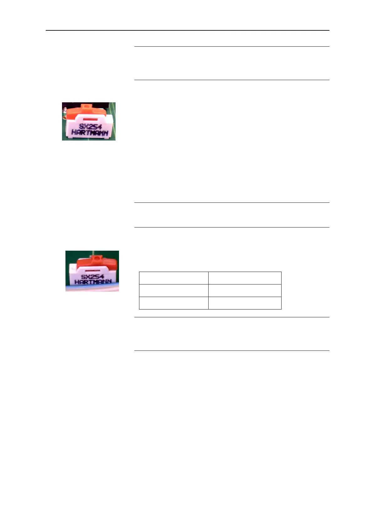
Slide switch T2
Use the slide switch T2 to determine the size of the indicator bot-
tle. The following indicator bottle sizes are possible:
Switch position
The status of the slide switch T2 is read after resetting the indicator
display to 100% and after a reset.
Plug connector J1
The plug connector J1 is a programming interface. It is not im-
portant for instrument operation.
Plug connector J2
The connection to the base circuit board is established via the plug
connector J2 using a ribbon cable.
Plug connector J3
The connection to the RS232 interface is established via the plug
connector J3 using a ribbon cable. Please refer to the section
entitled “Serial interface RS232” on page 24 for a detailed descrip-
tion.
Switch position right
(delivery status)
Switch position left
(delivery status)