Installation
18
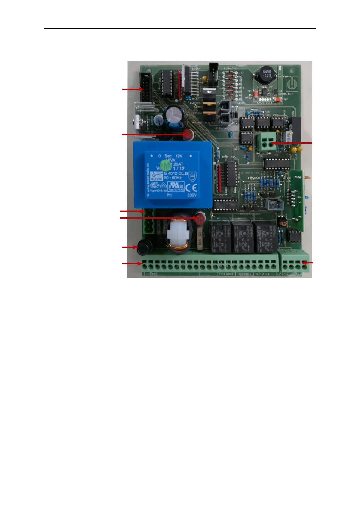
Base circuit board Testomat
®
808
The illustration above provides an overview of the design of the base
circuit board.
Plug connector J2
The connection to the controller board is established via the plug
connector J2 using a ribbon cable.
Plug connector J8
The power switch is connected at plug connector J8 .
Current interface
Please refer to the section entitled “Interfaces” on page 23 for a de-
scription of the current interface .