Description of the relay outputs
24
Current interface load
The current interface is galvanically decoupled. A maximum load of
500 Ohms should not be exceeded!
For faults and when using very long cables (approx. 20 m), a
screened cable should be used if possible.
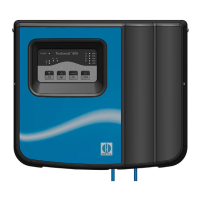
Serial interface RS232
The serial interface RS232 is located at the front of Testomat
®
808
(after opening the housing cover). Use a ribbon cable with a 9-pole
Sub-D connector to connect the plug J3 on the controller board to
RS232. Use this RS232 interface to connect a computer/notebook to
the controller board of Testomat
®
808 via a null modem cable and
update the instrument’s firmware.
Description of the relay outputs
All relay outputs are neutral contacts. This ensures that all connection
options are available. The switching of mains voltage and external
voltage, and the direct switching of inputs, e.g. a process controller,
can thus be realised. Please refer to the chapter entitled “Technical
data” on page 43 for the maximum load of the relays.
Relay K3 – fault message
Relay K3 is designed as a change-over contact and used for fault
messages indicating low water level, low indicator level, power failure
and measuring faults.
After several consecutive faulty measurements the relay K3 deac-
tivates and an error message is issued via the current interface.
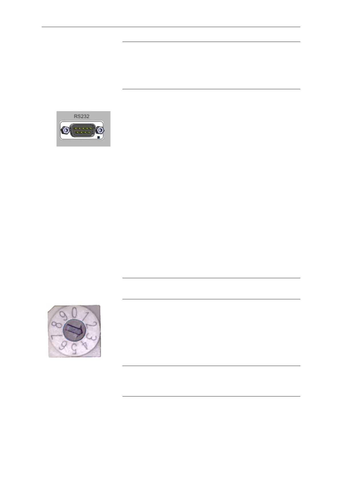
Relays K1 and K2
Two volt-free relay contacts are available to signal that a limit value
has been exceeded. Set the function of the relays via the switch posi-
tion of function key S7.
Switching functions of the relays K1 and K2
Switch position
The respective switch position is read after evaluating a measuring
result and after a reset.
The following switch positions are possible: