Battery Management Studio Software
www.ti.com
5.9 Device Control
Features are controlled by commands as described in the bq78350 TRM (SLUUAN7). One of the most
basic for operation as described in the quick start section is the FET enable which is toggled by the
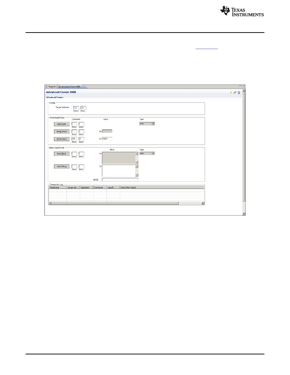
ManufacturerAccess() 0x0022 command. The Manufacturer Access commands may be sent using the
Advanced Comm SMB view and the Write Word button. An example is shown in Figure 16. A number of
the common commands are also available in buttons in the Commands view. Using the commands the
gauge may be controlled for test or setup for further evaluation. Refer to the bq78350 TRM for additional
information on the commands.
Figure 16. Advanced Comm SMB View
6 bq769x0 Circuit Module Use
The bq769x0 circuit module contains the bq769x0 IC and related circuitry to demonstrate the features of
the IC. Surface mount FETs are provided for the high current path. Thermistors provide for temperature
sensing on the board, 2 on the bq76930EVM, 3 on the bq76940EVM. Other components provide support
for the IC and connections to the board. Basic operation is described in the quick start guide. For details of
the circuit, refer to the physical construction section. Additional details may be described in the following
subsections.
6.1 Cell Simulator
The EVM includes a resistive cell simulator made up of 200 ohm series resistors. The top section of the
switch S3 connects the BATT+ node to the top of the resistor string. The bottom of the resistor string is
connected to BATT-. The individual cell taps are connected to the cell monitor signals by other sections of
the dip switch. When operating with a power supply all switch sections should be closed. When operating
with cells, all the dip switch sections should be open to prevent loading the cells and discharging the
battery. The cell simulator resistors are located on the bottom of the board. These may become warm
during operation. The orange LED near the dip switch indicates the cell simulator has power.
26
bq76930 and bq76940 Evaluation Module User's Guide SLVU925B–April 2014–Revised July 2014
Submit Documentation Feedback
Copyright © 2014, Texas Instruments Incorporated