CBLé System Guidebook 63
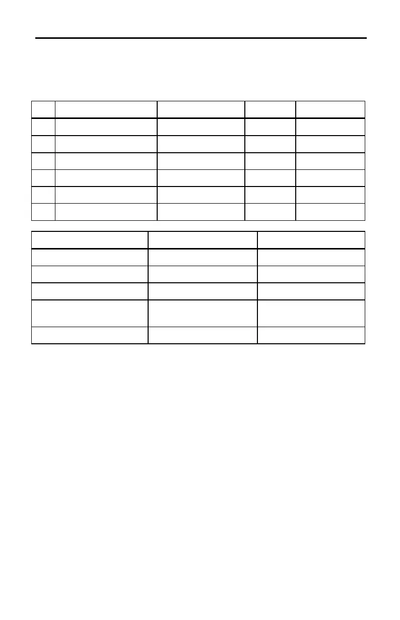
Connector Pinouts
The connectors on the probes used on the CBL are 6-pin, British
Telecom-style connectors.
Pin CH1, CH2, CH3 SONIC DIG IN DIG OUT
1 Vin (
CH1
,
CH2
only) Echo Clock-In Clock-Out
2 Gnd Init Gnd Gnd
3 Vres
AutoIDENT
D0 In D0 Out
4
AutoIDENT
+5 Volts DC D1 In D1 Out
5 +5 Volts DC Gnd D2 In D2 Out
6 Vin-low n/a D3 In D3 Out
Vin Vin-low
Channels:
CH1
and
CH2
only
CH1
,
CH2
,
CH3
Input signal: Analog data Analog data
Input range: ±10 Volts 0 to 5 Volts
Resolution (using CBL’s
10-bit A/D converter):
19.6 mV 5.6 mV
Input impedance: 740KJ to 2.0 Volts 748KJ to 0.03 Volts
Note: Due to a floating internal reference voltage, it is normal for the CBL to
measure about 30 mV (Vin-low) or 2.0 Volts (Vin) when no input is connected.
¦
Vres:
Output reference voltage from the CBL through a 15 Kohm resistor.
When using this feature, Vres should be tied to Vin-low and the value to be
measured should be connected between Vin-low and Gnd.
¦
Gnd:
Ground (common for all channels).
¦
AutoIDENT:
AutoIDENT
probe detection data input. (
AutoIDENT
resistor
connected from pin 4 to ground.)
¦
Echo:
Ultrasonic motion detector input.
¦
Init:
Distance initialization signal
¦
Clock-In:
External digital input clock.
¦
D0 In
to
D3 In:
Input pins for digital input pulses.
¦
Clock-Out:
Digital output clock.
¦
D0 Out
to
D3 Out:
Output pins for digital output pulses (refer to the example
on page 69).