21
SNAU217A–August 2017–Revised November 2017
Submit Documentation Feedback
Copyright © 2017, Texas Instruments Incorporated
Reference PRO
Appendix B
SNAU217A–August 2017–Revised November 2017
Reference PRO
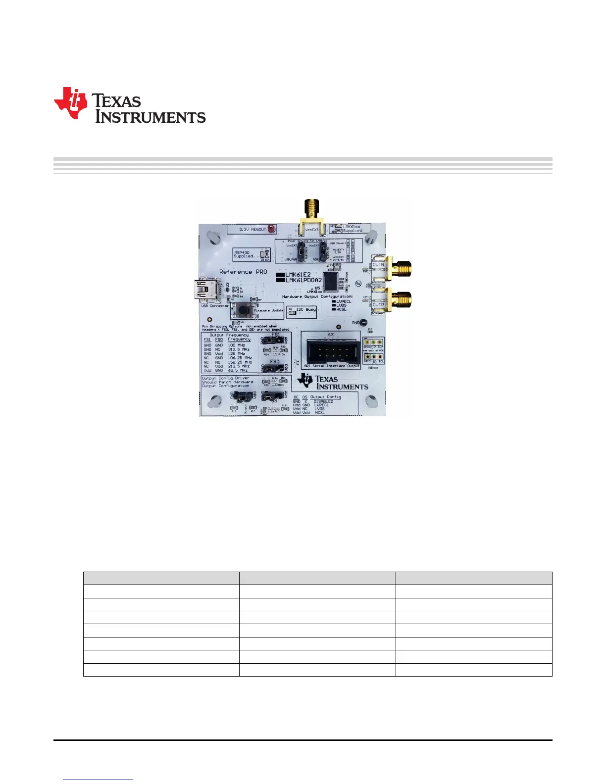
The Reference PRO board is used to program the LMX2572EVM and at the same time, provide a clean
reference clock to LMX2572EVM. The board has several control pins dedicated for control of output
format, output frequency, and output enable control. These control pins are configurable through the
jumpers by strapping the center pin to Vdd position or GND position. Connections from the Vdd position to
the device supply or from the GND position to the ground plane are connected by 1.5-kΩ resistors. By
default, the board is configured for 100-MHz LVPECL output. The power supply to Reference PRO is
obtained from the PC that is connecting to Reference PRO through the USB interface.
B.1 Output Frequency Selection
Jumpers FS1 and FS0 are used to set the output frequency.
Table 8. Reference PRO Output Frequency Selection
FS1 FS0 OUTPUT FREQUENCY (MHz)
GND GND 100
GND NC 312.5
GND Vdd 125
NC GND 106.25
NC NC 156.25
NC Vdd 212.5
Vdd GND 62.5