Setup
www.ti.com
4
SNAU217A–August 2017–Revised November 2017
Submit Documentation Feedback
Copyright © 2017, Texas Instruments Incorporated
LMX2572EVM Evaluation Instructions
2.2 Power Supply
Apply 3.3 V to V
CC
SMA connector. Acceptable supply voltage range is 3 V to 3.6 V. The maximum current
consumption in the most extreme configuration must not exceed 150 mA.
By default, the onboard DC-DC converter is not used.
2.3 Reference Clock
Connect OSCinP SMA connector with one of the outputs from Reference PRO using the SMA Male-to-
male adopter. OSCinM SMA connector is not connected to LMX2572 so it could be left open.
The EVM is configured for single-ended input with OSCin pin connected to OSCinP SMA connector and
OSCinM pin 50-Ω terminated onboard. If required, the EVM can be modified to operate with different clock
source in different configuration, see Appendix A for details.
Terminate the unused output of the Reference PRO board with a 50-Ω resistor or SMA load. By default,
the output clock from Reference PRO is a 100-MHz LVPECL clock. Appendix B has the details of
Reference PRO.
2.4 RF Output
Connect either RFoutAP or RFoutAM SMA connector to a signal analyzer. The unused connector must be
terminated with a 50-Ω resistor or SMA load. Output frequency is 3 GHz and the amplitude is about +2.5
dBm.
By default, the evaluation software, TICS Pro, has RFoutB power down. These SMA connectors could be
left open.
2.5 Programming
Connect ribbon cable from Reference PRO to LMX2572EVM.
Connect USB cable from a PC to USB port in Reference PRO. This provides power supply to Reference
PRO board and communication with TICS Pro. A firmware update may be required, see Appendix B for
details.
2.6 Evaluation Software
Download and install TICS Pro to a PC.
Run the software and follow the following steps to get started.
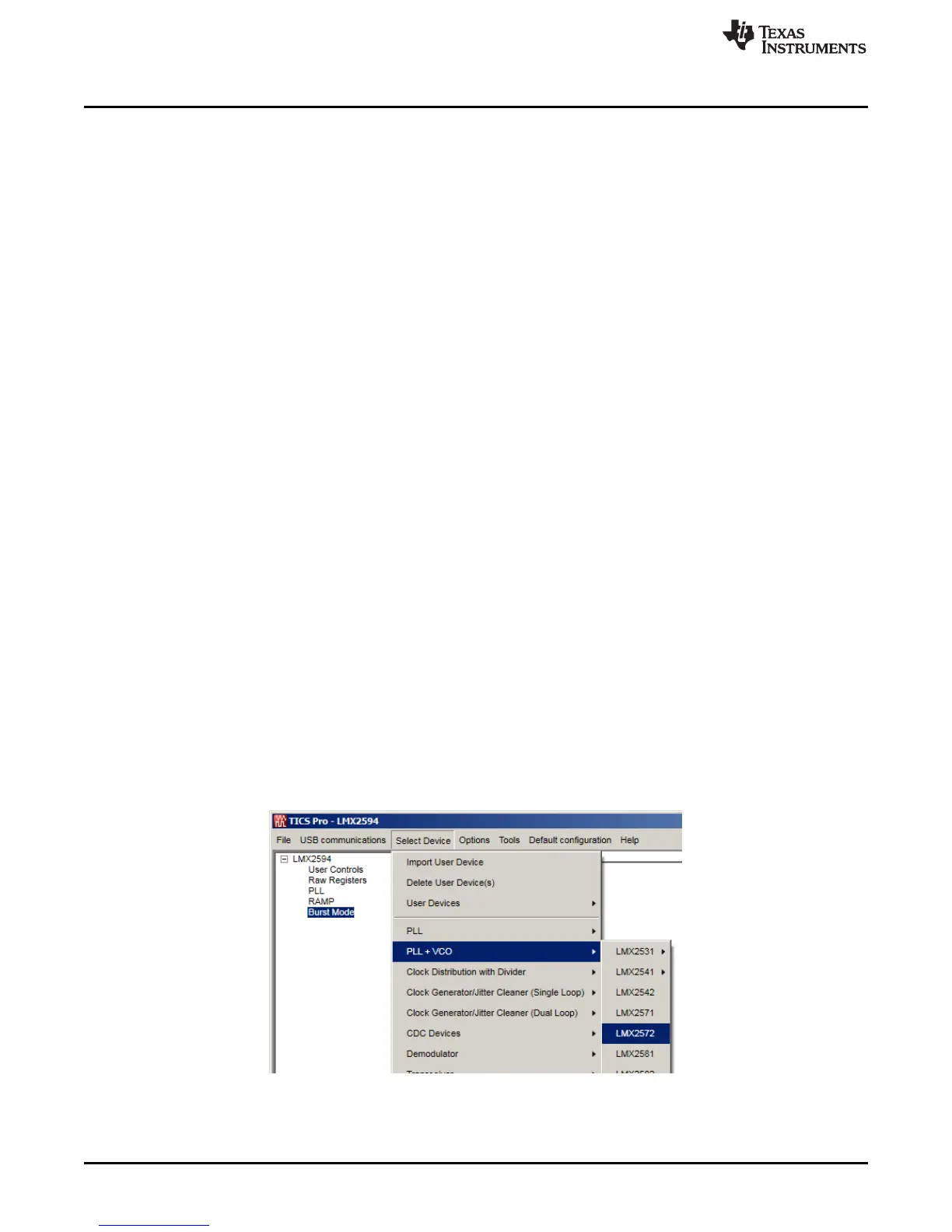
1. Go to "Select Device" → "PLL + VCO" → LMX2572.
Figure 2. Select Device in TICS Pro
2. Go to "Default Configuration" → "Default Mode xxxx-xx-xx".