www.ti.com
Setup
5
SNAU217A–August 2017–Revised November 2017
Submit Documentation Feedback
Copyright © 2017, Texas Instruments Incorporated
LMX2572EVM Evaluation Instructions
Figure 3. Default Mode
2.7 EVM Strap Options
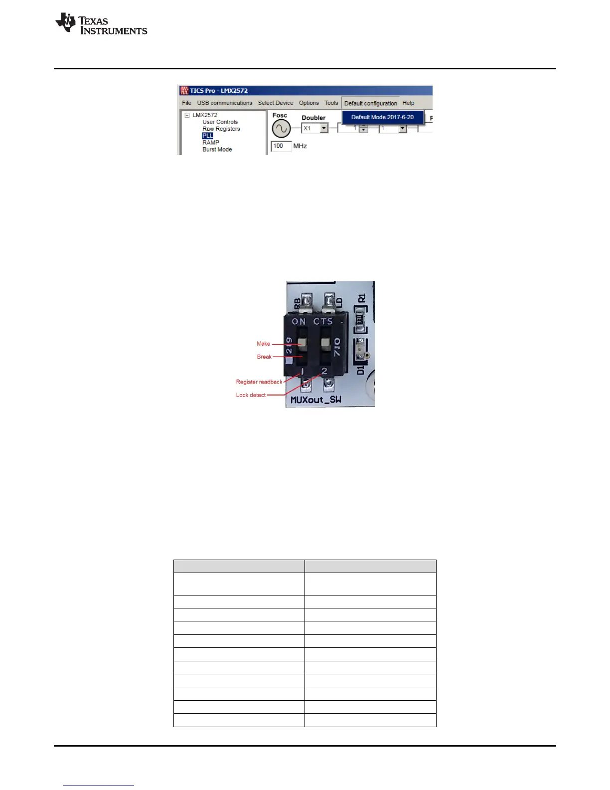
2.7.1 MUXout_SW
There are two switches in MUXout_SW. Switch 1 is used for register readback. Switch 2 is used to
provide a visual PLL lock status through the LED D1. By default, both switches are in the Make position.
To read back register in TICS Pro, set Switch 2 to the Break position.
Figure 4. MUXout_SW Switch
3 Typical Measurement
3.1 Default Configuration
3.1.1 Loop Filter
The parameters for the loop filter are:
Table 1. Loop Filter Configuration
PARAMETER VALUE
VCO frequency
Designed for 6 GHz, but works
over the whole frequency range
VCO gain 66 MHz/V
Effective charge pump gain 2500 µA
Phase detector frequency 100 MHz
Loop bandwidth 115 kHz
Phase margin 48 degrees
C1_LF, C3_LF Open
C2_LF 15 nF
C4_LF 2.2 nF
R2_LF 330 Ω
R3_LF, R4_LF 0 Ω