Typical Measurement
www.ti.com
6
SNAU217A–August 2017–Revised November 2017
Submit Documentation Feedback
Copyright © 2017, Texas Instruments Incorporated
LMX2572EVM Evaluation Instructions
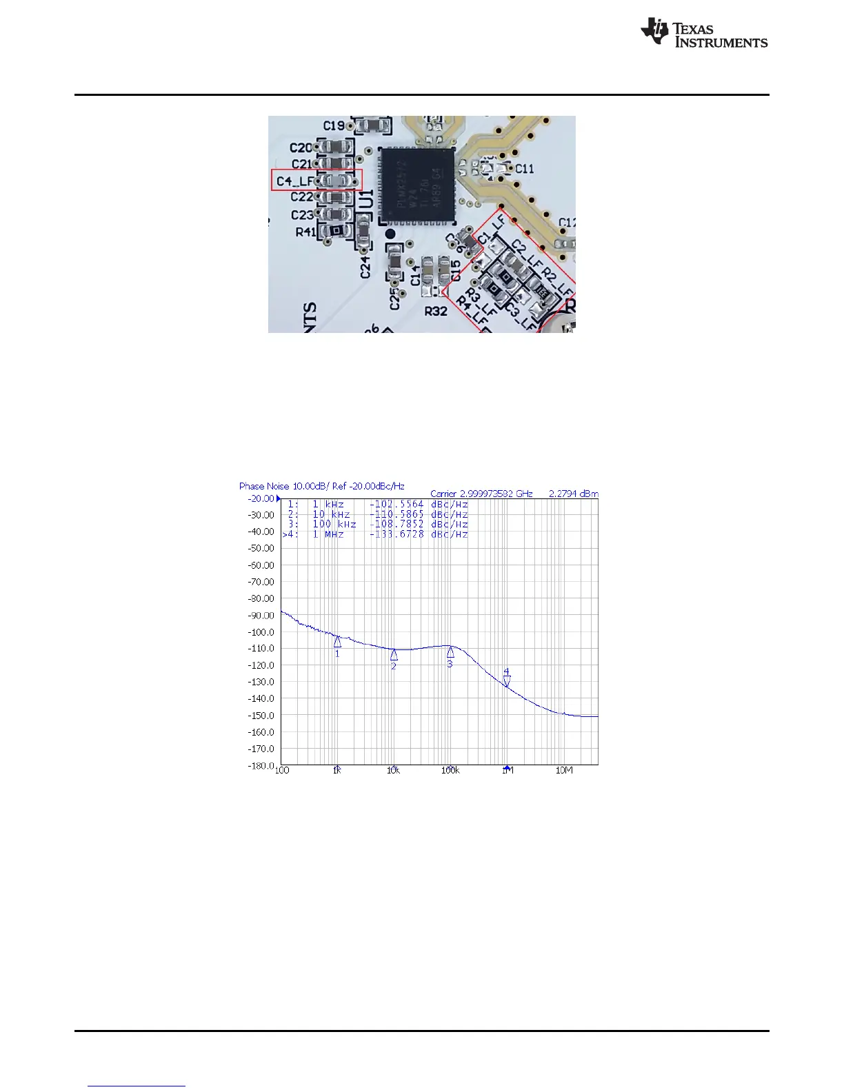
Figure 5. Loop Filter
3.1.2 Typical Output
1. Follow Section 2 to setup the evaluation.
2. Click "Write All Registers" to write all the registers to LMX2572.
Default output is 3 GHz.
Figure 6. Default Output
3.2 Additional Tests
3.2.1 Phase Adjustment
The phase of the RF output signal can be adjusted as follows:
Phase shift in degree = 360° × (MASH_SEED / PLL_DEN) × (P / CHDIV), where P = 2 when
VCO_PHASE_SYNC_EN = 1, else P = 1.
Here is an example.