35
TMS320F28069
,
TMS320F28068
,
TMS320F28067
,
TMS320F28066
TMS320F28065, TMS320F28064, TMS320F28063, TMS320F28062
www.ti.com
SPRS698F –NOVEMBER 2010–REVISED MARCH 2016
Submit Documentation Feedback
Product Folder Links: TMS320F28069 TMS320F28068 TMS320F28067 TMS320F28066 TMS320F28065
TMS320F28064 TMS320F28063 TMS320F28062
SpecificationsCopyright © 2010–2016, Texas Instruments Incorporated
(1) Write/erase operations outside of the temperature ranges indicated are not specified and may affect the endurance numbers.
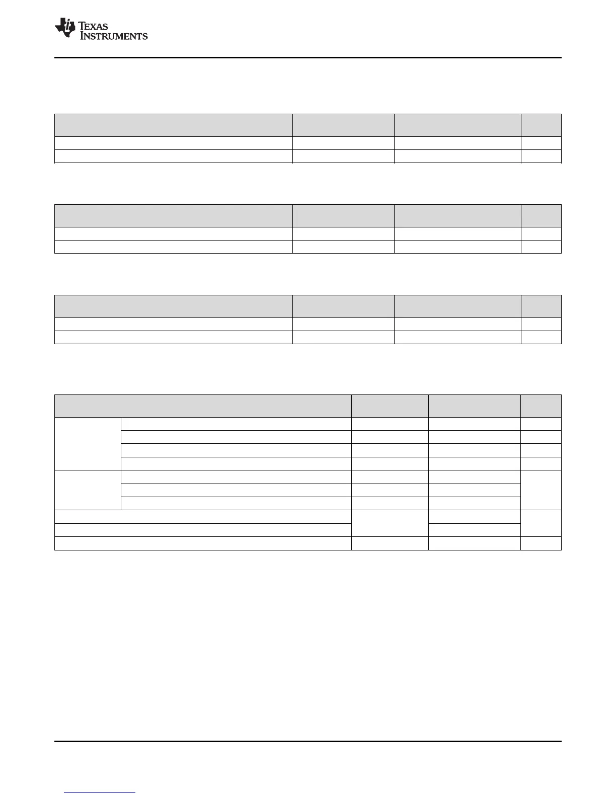
5.14 Flash Timing
Table 5-11. Flash/OTP Endurance for T Temperature Material
(1)
ERASE/PROGRAM
TEMPERATURE
MIN TYP MAX UNIT
N
f
Flash endurance for the array (write/erase cycles) 0°C to 105 ° C (ambient) 20000 50000 cycles
N
OTP
OTP endurance for the array (write cycles) 0°C to 30°C (ambient) 1 write
(1) Write/erase operations outside of the temperature ranges indicated are not specified and may affect the endurance numbers.
Table 5-12. Flash/OTP Endurance for S Temperature Material
(1)
ERASE/PROGRAM
TEMPERATURE
MIN TYP MAX UNIT
N
f
Flash endurance for the array (write/erase cycles) 0°C to 125 ° C (ambient) 20000 50000 cycles
N
OTP
OTP endurance for the array (write cycles) 0°C to 30°C (ambient) 1 write
(1) Write/erase operations outside of the temperature ranges indicated are not specified and may affect the endurance numbers.
(2) The "Q" temperature option is not available on the 2806xU devices.
Table 5-13. Flash/OTP Endurance for Q Temperature Material
(1)(2)
ERASE/PROGRAM
TEMPERATURE
MIN TYP MAX UNIT
N
f
Flash endurance for the array (write/erase cycles) –40°C to 125°C (ambient) 20000 50000 cycles
N
OTP
OTP endurance for the array (write cycles) –40°C to 30°C (ambient) 1 write
(1) The on-chip flash memory is in an erased state when the device is shipped from TI. As such, erasing the flash memory is not required
before programming, when programming the device for the first time. However, the erase operation is needed on all subsequent
programming operations.
(2) Typical parameters as seen at room temperature including function call overhead, with all peripherals off. It is important to maintain a
stable power supply during the entire flash programming process. It is conceivable that device current consumption during flash
programming could be higher than normal operating conditions. The power supply used should ensure V
MIN
on the supply rails at all
times, as specified in the Recommended Operating Conditions of the data sheet. Any brown-out or interruption to power during
erasing/programming could potentially corrupt the password locations and lock the device permanently. Powering a target board (during
flash programming) through the USB port is not recommended, as the port may be unable to respond to the power demands placed
during the programming process.
Table 5-14. Flash Parameters at 90-MHz SYSCLKOUT
PARAMETER
TEST
CONDITIONS
MIN TYP MAX UNIT
Program Time
16-Bit Word 50 μs
16K Sector 500 ms
8K Sector 250 ms
4K Sector 125 ms
Erase Time
(1)
16K Sector 2
s8K Sector 2
4K Sector 2
I
DDP
(2)
V
DD
current consumption during Erase/Program cycle
VREG disabled
80
mA
I
DDIOP
(2)
V
DDIO
current consumption during Erase/Program cycle 60
I
DDIOP
(2)
V
DDIO
current consumption during Erase/Program cycle VREG enabled 120 mA