20
TMS320F28069
,
TMS320F28068
,
TMS320F28067
,
TMS320F28066
TMS320F28065, TMS320F28064, TMS320F28063, TMS320F28062
SPRS698F –NOVEMBER 2010–REVISED MARCH 2016
www.ti.com
Submit Documentation Feedback
Product Folder Links: TMS320F28069 TMS320F28068 TMS320F28067 TMS320F28066 TMS320F28065
TMS320F28064 TMS320F28063 TMS320F28062
Specifications Copyright © 2010–2016, Texas Instruments Incorporated
(1) Group 2 pins are as follows: GPIO16, GPIO17, GPIO18, GPIO19, GPIO28, GPIO29, GPIO36, GPIO37.
(2) The "Q" temperature option is not available on the 2806xU devices.
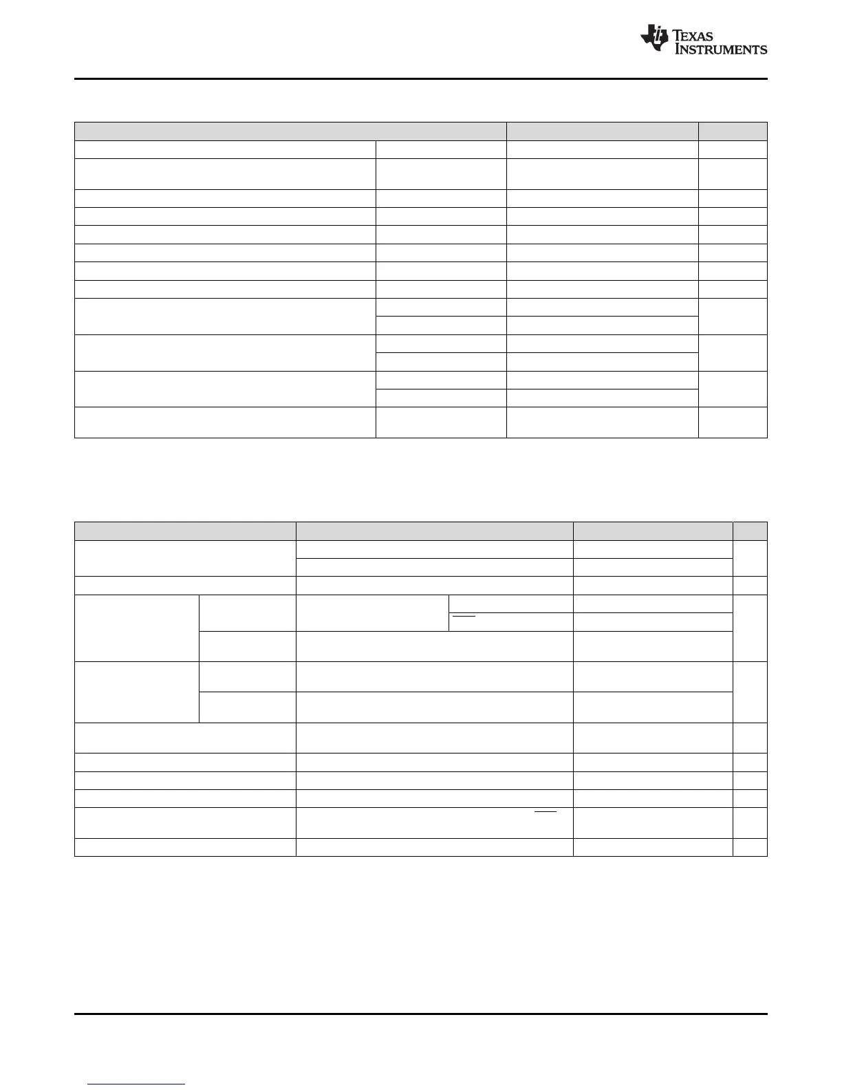
5.4 Recommended Operating Conditions
MIN NOM MAX UNIT
Device supply voltage, I/O, V
DDIO
2.97 3.3 3.63 V
Device supply voltage CPU, V
DD
(When internal VREG is
disabled and 1.8 V is supplied externally)
1.71 1.8 1.995
V
Supply ground, V
SS
0 V
Analog supply voltage, V
DDA
2.97 3.3 3.63 V
Analog ground, V
SSA
0 V
Device clock frequency (system clock) 2 90 MHz
High-level input voltage, V
IH
(3.3 V) 2 V
DDIO
+ 0.3 V
Low-level input voltage, V
IL
(3.3 V) V
SS
– 0.3 0.8 V
High-level output source current, V
OH
= V
OH(MIN)
, I
OH
All GPIO/AIO pins –4
mA
Group 2
(1)
–8
Low-level output sink current, V
OL
= V
OL(MAX)
, I
OL
All GPIO/AIO pins 4
mA
Group 2
(1)
8
Junction temperature, T
J
T version –40 105
°C
S version –40 125
Ambient temperature, T
A
Q version
(2)
(Q100 qualification)
–40 125
°C
(1) When the on-chip VREG is used, its output is monitored by the POR/BOR circuit, which will reset the device should the core voltage
(V
DD
) go out of range.
5.5 Electrical Characteristics
(1)
over recommended operating conditions (unless otherwise noted)
PARAMETER TEST CONDITIONS MIN TYP MAX UNIT
V
OH
High-level output voltage
I
OH
= I
OH
MAX 2.4
V
I
OH
= 50 μA V
DDIO
– 0.2
V
OL
Low-level output voltage I
OL
= I
OL
MAX 0.4 V
I
IL
Input current
(low level)
Pin with pullup
enabled
V
DDIO
= 3.3 V, V
IN
= 0 V
All GPIO –80 –140 –205
μA
XRS pin –230 –300 –375
Pin with pulldown
enabled
V
DDIO
= 3.3 V, V
IN
= 0 V ±2
I
IH
Input current
(high level)
Pin with pullup
enabled
V
DDIO
= 3.3 V, V
IN
= V
DDIO
±2
μA
Pin with pulldown
enabled
V
DDIO
= 3.3 V, V
IN
= V
DDIO
28 50 80
I
OZ
Output current, pullup or
pulldown disabled
V
O
= V
DDIO
or 0 V ±2 μA
C
I
Input capacitance 2 pF
V
DDIO
BOR trip point Falling V
DDIO
2.50 2.78 2.96 V
V
DDIO
BOR hysteresis 35 mV
Supervisor reset release delay
time
Time after BOR/POR/OVR event is removed to XRS
release
400 800 μs
VREG V
DD
output Internal VREG on 1.9 V