73
TMS320F28069
,
TMS320F28068
,
TMS320F28067
,
TMS320F28066
TMS320F28065, TMS320F28064, TMS320F28063, TMS320F28062
www.ti.com
SPRS698F –NOVEMBER 2010–REVISED MARCH 2016
Submit Documentation Feedback
Product Folder Links: TMS320F28069 TMS320F28068 TMS320F28067 TMS320F28066 TMS320F28065
TMS320F28064 TMS320F28063 TMS320F28062
Detailed DescriptionCopyright © 2010–2016, Texas Instruments Incorporated
(1) The Exit column lists which signals or under what conditions the low power mode is exited. A low signal, on any of the signals, exits the
low power condition. This signal must be kept low long enough for an interrupt to be recognized by the device. Otherwise, the low-power
mode will not be exited and the device will go back into the indicated low power mode.
(2) The JTAG port can still function even if the CPU clock (CLKIN) is turned off.
(3) The WDCLK must be active for the device to go into HALT mode.
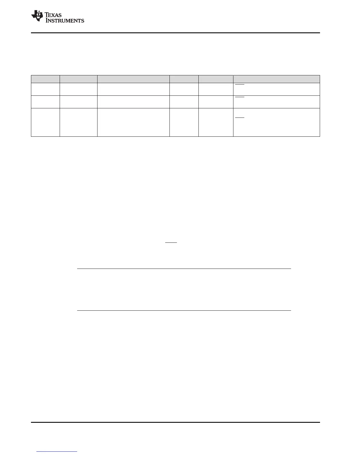
6.7 Low-power Modes Block
Table 6-16 summarizes the various modes.
Table 6-16. Low-power Modes
MODE LPMCR0(1:0) OSCCLK CLKIN SYSCLKOUT EXIT
(1)
IDLE 00 On On On
XRS, CPU-watchdog interrupt, any
enabled interrupt
STANDBY 01
On
(CPU-watchdog still running)
Off Off
XRS, CPU-watchdog interrupt, GPIO
Port A signal, debugger
(2)
HALT
(3)
1X
Off
(on-chip crystal oscillator and
PLL turned off, zero-pin oscillator
and CPU-watchdog state
dependent on user code.)
Off Off
XRS, GPIO Port A signal, debugger
(2)
,
CPU-watchdog
The various low-power modes operate as follows:
IDLE Mode: This mode is exited by any enabled interrupt that is recognized by the
processor. The LPM block performs no tasks during this mode as long as
the LPMCR0(LPM) bits are set to 0,0.
STANDBY Mode: Any GPIO port A signal (GPIO[31:0]) can wake the device from STANDBY
mode. The user must select which signals will wake the device in the
GPIOLPMSEL register. The selected signals are also qualified by the
OSCCLK before waking the device. The number of OSCCLKs is specified in
the LPMCR0 register.
HALT Mode: CPU-watchdog, XRS, and any GPIO port A signal (GPIO[31:0]) can wake
the device from HALT mode. The user selects the signal in the
GPIOLPMSEL register.
NOTE
The low-power modes do not affect the state of the output pins (PWM pins included). They
will be in whatever state the code left them in when the IDLE instruction was executed. See
the Systems Control and Interrupts chapter of the TMS320x2806x Piccolo Technical
Reference Manual (SPRUH18) for more details.