TRST
TMS
TDI
TDO
TCK
V
DDIO
MCU
EMU0
EMU1
TRST
TMS
TDI
TDO
TCK
TCK_RET
13
14
2
1
3
7
11
9
6 inches or less
PD
GND
GND
GND
GND
GND
5
4
6
8
10
12
JTAG Header
V
DDIO
27
TMS320F28069
,
TMS320F28068
,
TMS320F28067
,
TMS320F28066
TMS320F28065, TMS320F28064, TMS320F28063, TMS320F28062
www.ti.com
SPRS698F –NOVEMBER 2010–REVISED MARCH 2016
Submit Documentation Feedback
Product Folder Links: TMS320F28069 TMS320F28068 TMS320F28067 TMS320F28066 TMS320F28065
TMS320F28064 TMS320F28063 TMS320F28062
SpecificationsCopyright © 2010–2016, Texas Instruments Incorporated
5.8 Thermal Design Considerations
Based on the end application design and operational profile, the I
DD
and I
DDIO
currents could vary.
Systems that exceed the recommended maximum power dissipation in the end product may require
additional thermal enhancements. Ambient temperature (T
A
) varies with the end application and product
design. The critical factor that affects reliability and functionality is T
J
, the junction temperature, not the
ambient temperature. Hence, care should be taken to keep T
J
within the specified limits. T
case
should be
measured to estimate the operating junction temperature T
J
. T
case
is normally measured at the center of
the package top-side surface. The thermal application report IC Package Thermal Metrics (SPRA953)
helps to understand the thermal metrics and definitions.
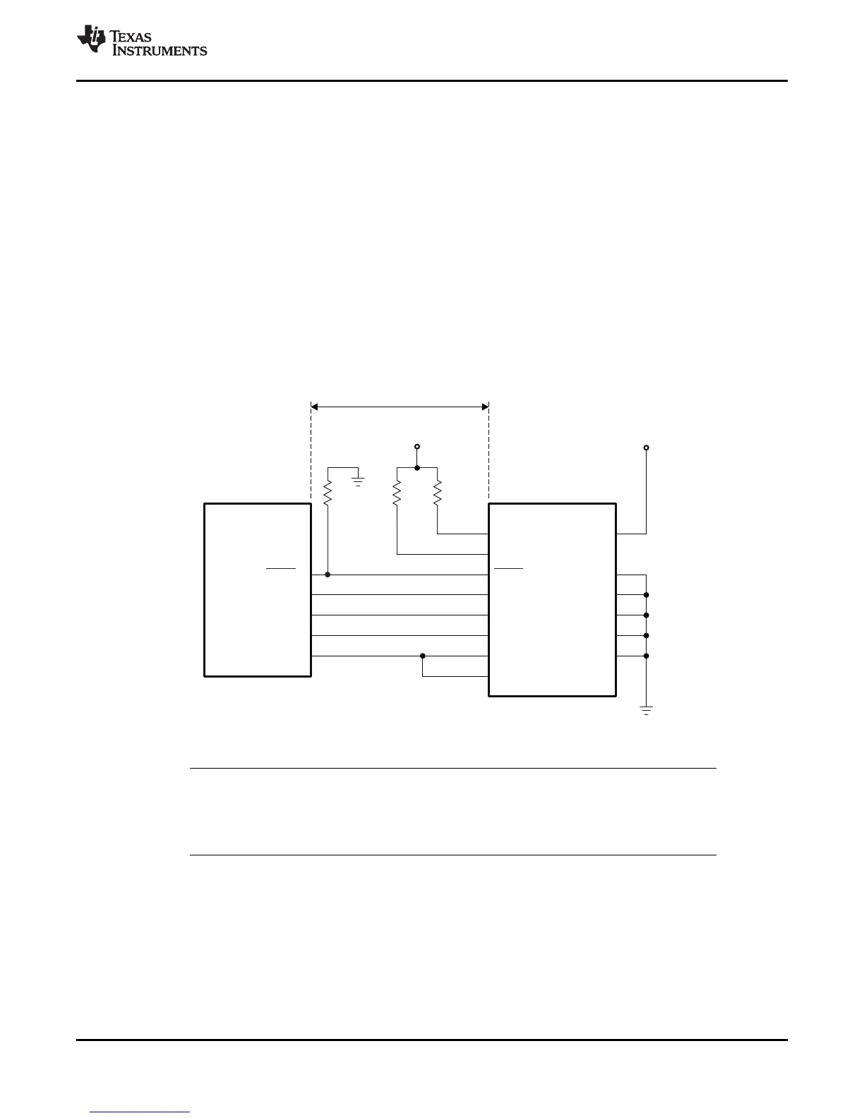
5.9 Emulator Connection Without Signal Buffering for the MCU
Figure 5-3 shows the connection between the MCU and JTAG header for a single-processor configuration.
If the distance between the JTAG header and the MCU is greater than 6 inches, the emulation signals
must be buffered. If the distance is less than 6 inches, buffering is typically not needed. Figure 5-3 shows
the simpler, no-buffering situation. For the pullup and pulldown resistor values, see Section 4.2.
A. See Figure 6-54 for JTAG/GPIO multiplexing.
Figure 5-3. Emulator Connection Without Signal Buffering for the MCU
NOTE
The 2806x devices do not have EMU0/EMU1 pins. For designs that have a JTAG Header
onboard, the EMU0/EMU1 pins on the header must be tied to V
DDIO
through a 4.7-kΩ
(typical) resistor.