32
TMS320F28069
,
TMS320F28068
,
TMS320F28067
,
TMS320F28066
TMS320F28065, TMS320F28064, TMS320F28063, TMS320F28062
SPRS698F –NOVEMBER 2010–REVISED MARCH 2016
www.ti.com
Submit Documentation Feedback
Product Folder Links: TMS320F28069 TMS320F28068 TMS320F28067 TMS320F28066 TMS320F28065
TMS320F28064 TMS320F28063 TMS320F28062
Specifications Copyright © 2010–2016, Texas Instruments Incorporated
(1) Lower LSPCLK will reduce device power consumption.
(2) This is the default reset value if SYSCLKOUT = 90 MHz.
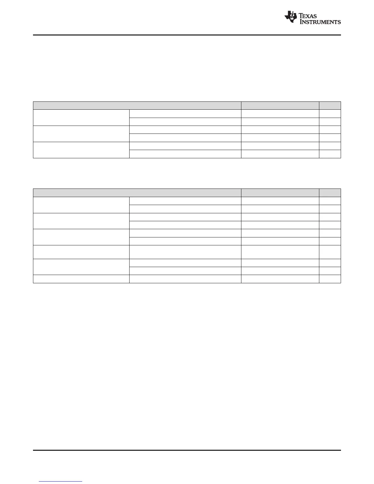
5.13 Clock Specifications
5.13.1 Device Clock Table
This section provides the timing requirements and switching characteristics for the various clock options
available on the 2806x MCUs. Table 5-5 lists the cycle times of various clocks.
Table 5-5. 2806x Clock Table and Nomenclature (90-MHz Devices)
MIN NOM MAX UNIT
SYSCLKOUT
t
c(SCO)
, Cycle time 11.11 500 ns
Frequency 2 90 MHz
LSPCLK
(1)
t
c(LCO)
, Cycle time 11.11 44.4
(2)
ns
Frequency 22.5
(2)
90 MHz
ADC clock
t
c(ADCCLK)
, Cycle time 22.22 ns
Frequency 45 MHz
(1) The PLLLOCKPRD register must be updated based on the number of OSCCLK cycles. If the zero-pin internal oscillators (10 MHz) are
used as the clock source, then the PLLLOCKPRD register must be written with a value of 10,000 (minimum).
Table 5-6. Device Clocking Requirements/Characteristics
MIN NOM MAX UNIT
On-chip oscillator (X1/X2 pins)
(Crystal/Resonator)
t
c(OSC)
, Cycle time 50 200 ns
Frequency 5 20 MHz
External oscillator/clock source
(XCLKIN pin) — PLL Enabled
t
c(CI)
, Cycle time (C8) 33.3 200 ns
Frequency 5 30 MHz
External oscillator/clock source
(XCLKIN pin) — PLL Disabled
t
c(CI)
, Cycle time (C8) 11.11 250 ns
Frequency 4 90 MHz
Limp mode SYSCLKOUT
(with /2 enabled)
Frequency range 1 to 5 MHz
XCLKOUT
t
c(XCO)
, Cycle time (C1) 44.44 2000 ns
Frequency 0.5 22.5 MHz
PLL lock time
(1)
t
p
1 ms