OSCCLK
SYSCLKOUT
Write to PLLCR
OSCCLK * 2
(Current CPU
Frequency)
OSCCLK/2
(CPU frequency while PLL is stabilizing
with the desired frequency. This period
(PLL lock-up time t ) is 1 ms long.)
p
OSCCLK * 4
(Changed CPU frequency)
31
TMS320F28069
,
TMS320F28068
,
TMS320F28067
,
TMS320F28066
TMS320F28065, TMS320F28064, TMS320F28063, TMS320F28062
www.ti.com
SPRS698F –NOVEMBER 2010–REVISED MARCH 2016
Submit Documentation Feedback
Product Folder Links: TMS320F28069 TMS320F28068 TMS320F28067 TMS320F28066 TMS320F28065
TMS320F28064 TMS320F28063 TMS320F28062
SpecificationsCopyright © 2010–2016, Texas Instruments Incorporated
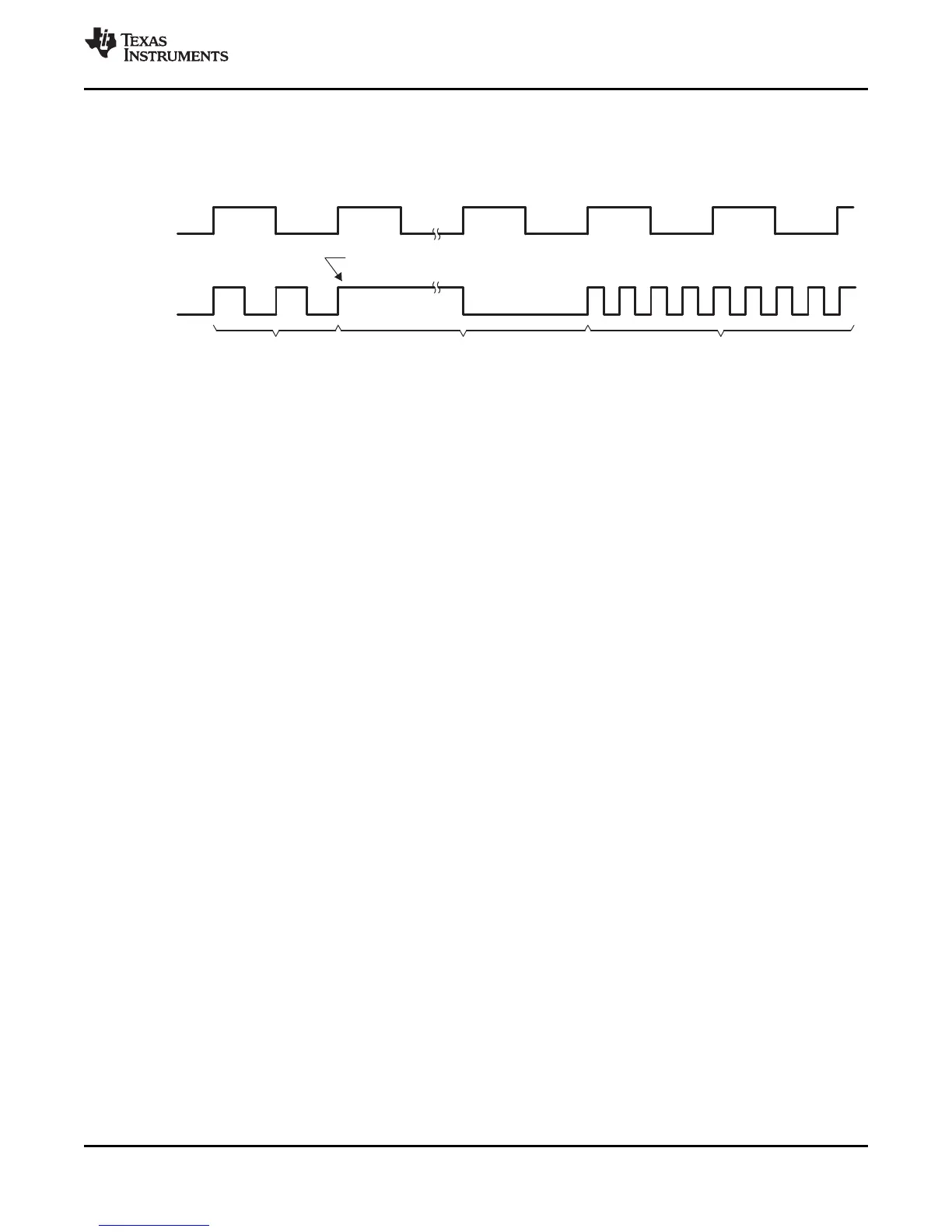
Figure 5-7 shows an example for the effect of writing into PLLCR register. In the first phase, PLLCR =
0x0004 and SYSCLKOUT = OSCCLK × 2. The PLLCR is then written with 0x0008. Right after the PLLCR
register is written, the PLL lock-up phase begins. During this phase, SYSCLKOUT = OSCCLK/2. After the
PLL lock-up is complete, SYSCLKOUT reflects the new operating frequency, OSCCLK × 4.
Figure 5-7. Example of Effect of Writing Into PLLCR Register