X2X1
Crystal
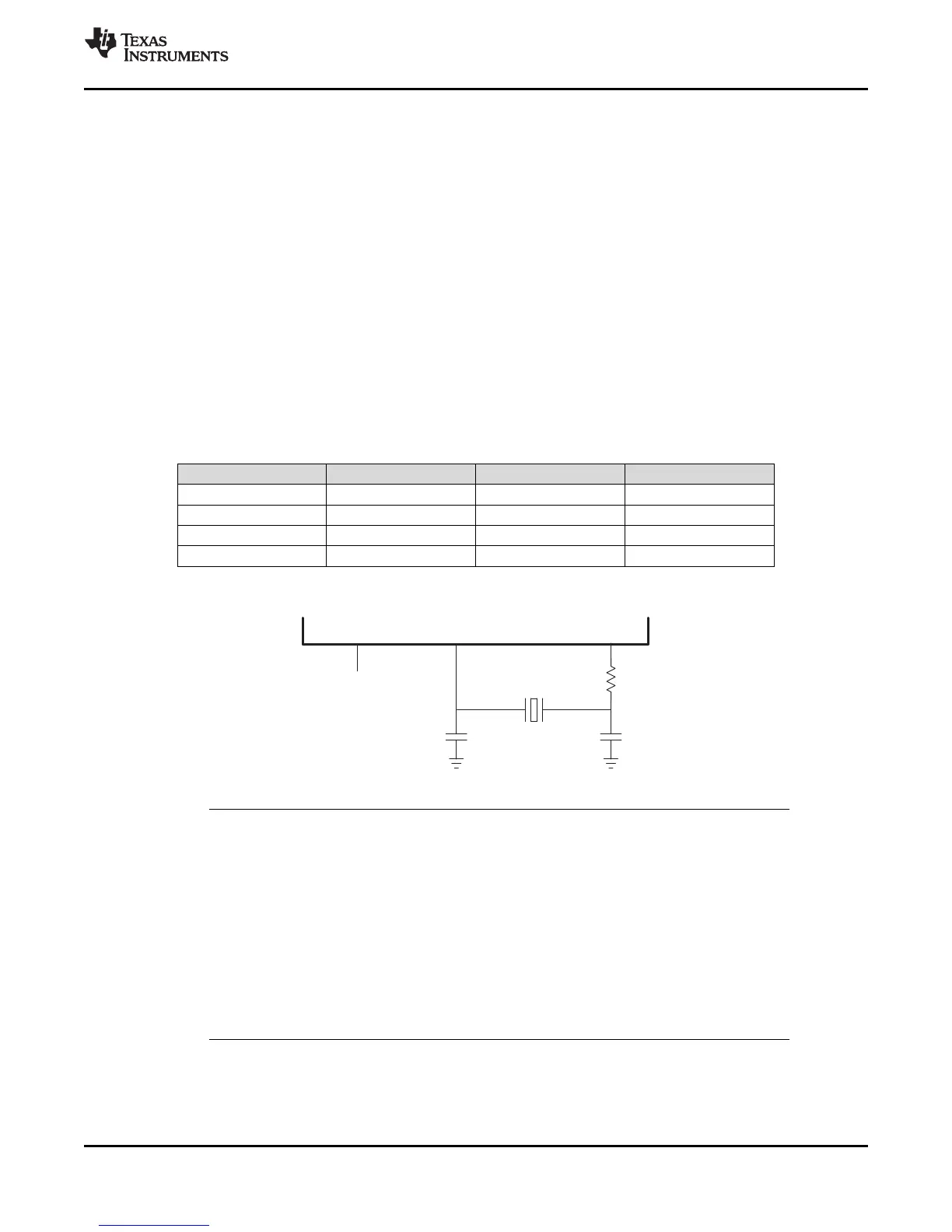
XCLKIN/GPIO19/38
Turn off
XCLKIN path
in CLKCTL
register
R
d
C
L1
C
L2
67
TMS320F28069
,
TMS320F28068
,
TMS320F28067
,
TMS320F28066
TMS320F28065, TMS320F28064, TMS320F28063, TMS320F28062
www.ti.com
SPRS698F –NOVEMBER 2010–REVISED MARCH 2016
Submit Documentation Feedback
Product Folder Links: TMS320F28069 TMS320F28068 TMS320F28067 TMS320F28066 TMS320F28065
TMS320F28064 TMS320F28063 TMS320F28062
Detailed DescriptionCopyright © 2010–2016, Texas Instruments Incorporated
6.6.1 Internal Zero Pin Oscillators
The F2806x devices contain two independent internal zero pin oscillators. By default both oscillators are
turned on at power up, and internal oscillator 1 is the default clock source at this time. For power savings,
unused oscillators may be powered down by the user. The center frequency of these oscillators is
determined by their respective oscillator trim registers, written to in the calibration routine as part of the
boot ROM execution. See Section 6.9 for more information on these oscillators.
6.6.2 Crystal Oscillator Option
The on-chip crystal oscillator X1 and X2 pins are 1.8-V level signals and must never have 3.3-V level
signals applied to them. If a system 3.3-V external oscillator is to be used as a clock source, it should be
connected to the XCLKIN pin only. The X1 pin is not intended to be used as a single-ended clock input, it
should be used with X2 and a crystal.
The typical specifications for the external quartz crystal (fundamental mode, parallel resonant) are listed in
Table 6-12. Furthermore, ESR range = 30 to 150 Ω.
(1) C
shunt
should be less than or equal to 5 pF.
Table 6-12. Typical Specifications for External Quartz Crystal
(1)
FREQUENCY (MHz) R
d
(Ω) C
L1
(pF) C
L2
(pF)
5 2200 18 18
10 470 15 15
15 0 15 15
20 0 12 12
Figure 6-12. Using the On-chip Crystal Oscillator
NOTE
1. C
L1
and C
L2
are the total capacitance of the circuit board and components excluding the
IC and crystal. The value is usually approximately twice the value of the load capacitance
of the crystal.
2. The load capacitance of the crystal is described in the crystal specifications of the
manufacturers.
3. TI recommends that customers have the resonator/crystal vendor characterize the
operation of their device with the MCU chip. The resonator/crystal vendor has the
equipment and expertise to tune the tank circuit. The vendor can also advise the
customer regarding the proper tank component values that will produce proper start up
and stability over the entire operating range.