AS 680/682
Description, Operation and Maintenance Maintenance and Repair
ADS−B
7−7Ed. 10.07
7.2 FAULT LOCATION
7.2.1 General
To perform maintenance activities, the user must login at the RCMS or LCMS. Fault detection is pos-
sible down to LRU level (subsystem or selected subassemblies in SPU) to support the replacement
of the failing LRU.
7.2.2 Power Supply, Subsystem Indicators
The BIT of the individual subsystems indicates faulty operating voltages, so that the defective subsys-
tem can be defined and replaced. Before replacing the AC/DC converter (or optional DC/DC conver-
ter) check external power supply fed to the equipment. Before locating a fault, try to define roughly
the defective functional LRU, i.e. the SPU (with RXU, GTS, SPB, SBC), Site Monitor, Data Switch and
UPS. Check also external equipment:
− Antenna and antenna connections,
− Ethernet interface to ground network
− DC or mains (if applicable) power supply cable
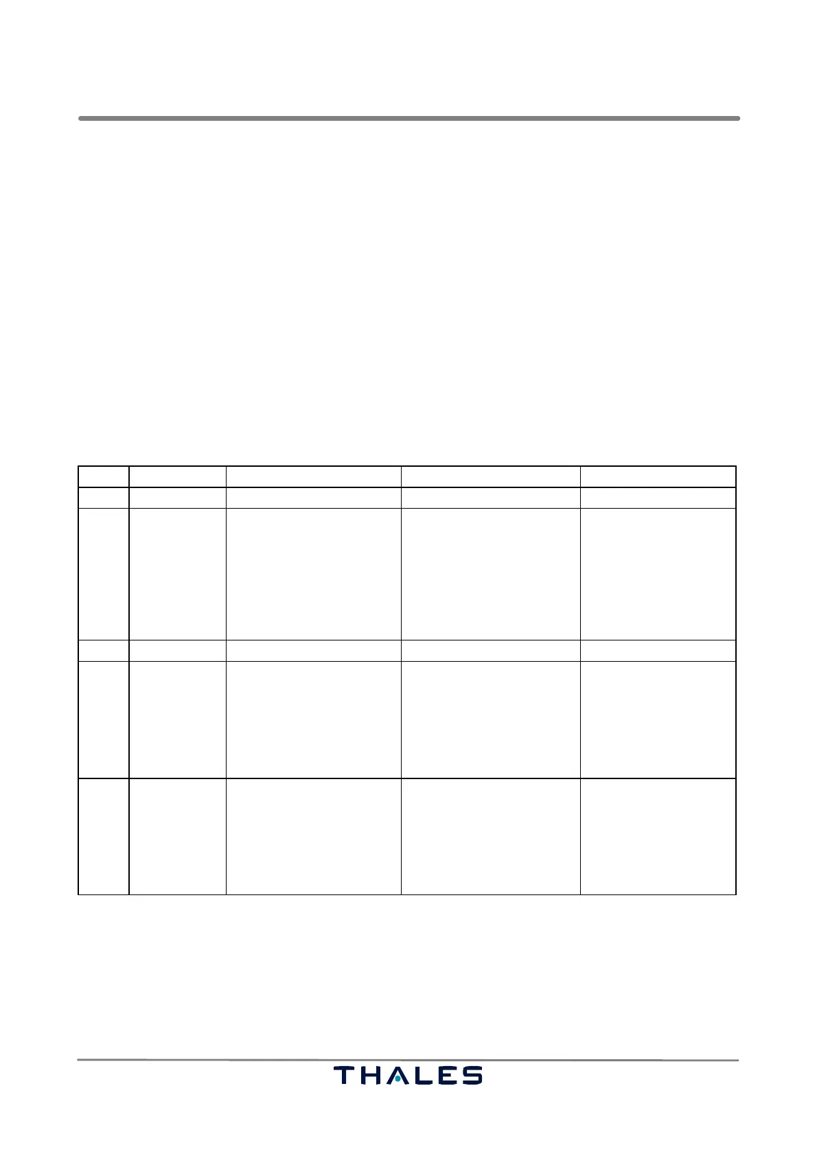
A first localization is done by evaluating the Fail or Power indicators (LED) on the various subsystems.
Step Fault A B C
All
Power Supply Power−LED off?
Fault−LED on?
Device switched to ON?
Power available?
AC input power available?
If yes, check fuses (also of
mains supply socket strip:
Replace once if blown.
If ok, AC/DC converter or
other subassembly may
cause the fault: replace
the resp. subassembly.
SPU
1 DC/DC conv. Power−LED off?
Fault−LED on?
DC switched to ON?
DC power available?
DC input power available?
If yes, check fuses:
Replace once if blown.
If ok, DC/DC converter or
other subassembly may
cause the fault: replace
the resp. subassembly.
2 AC/DC conv.
(optional)
Power−LED off?
Fault−LED on?
AC switched to ON?
AC power available?
AC input power available?
If yes, check fuses:
Replace once if blown.
If ok, AC/DC converter or
other subassembly may
cause the fault: replace
the resp. subassembly.
7.2.3 Performing Tests
This section describes recommended test procedures to localise a faulty component presuming fol-
lowing fault characteristics:
− BITE Failure (indication "red") refer to section 7.2.3.1
− No Network Connection refer to section 7.2.3.2
− No Raw Data refer to section 7.2.3.3
− No Asterix Data refer to section 7.2.3.4
 Loading...