AS 680/682
Description, Operation and Maintenance Subsystem Description
ADS−B
2−21Ed. 10.07
2.3 PERIPHERAL EQUIPMENT
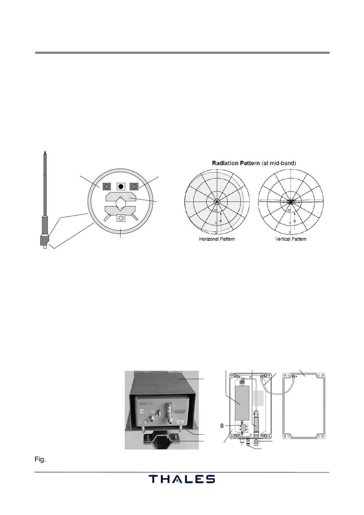
2.3.1 Omnidirectional Antenna
See Figs. 2−2, 2−23.
The ADS−B RX antenna is derived from a well−proven world wide deployed DME antenna. It consists
of a number of identical, decoupled half−wave dipoles and phase feeding cables and transformer.
Its gain is about 11.5 dBi. The high gain of this antenna is achieved by a vertically focussed diagram
that is elevated by an uptilt of ca. 2°. It is important that the antenna is mounted to an exact upright
position so that the main lobe remains close to the horizon in all directions.
bottom view, connectors
RF out
RF test in (GS1)
RF test in (GS2)
power supply for obstruction lights
not used
mounting
clamp
Radome cover
OL
M1 M2
ANTENNA
connector
NNN
Fig. 2−23 Omnidirectional antenna
2.3.2 Antenna Amplifier Unit (AAU) with mounting Kit and Weather Protection
See Fig. 2−24.
The AAU is mounted as close as possible to the omnidirectional antenna (cable length <2 m). It
serves to optimize the system signal−to−noise ratio and to compensate cable attenuation. It has a
gain of approx. 15 dB and a noise figure below 0.7 dB. It is DC powered via the RF output cable from
the Ground Station receiver unit RXU. The DC supply can be interrupted with a jumper on the RXU
board. A passive lightning protector stub and a 1090 MHz band−pass filter are also part of the assem-
bly as shown in Fig. 2−24 below. To avoid overload an optional HF limiter at the RF input is available.
NOTE: If the AAU is not powered up it will not provide gain but will attenuate the signal. Therefore
it is crucial to verify that the supply voltage is available.
1
1 Filter (optional)
2 Input limiter (optional)
3 Earthing cable between
housing base and cover
4 Input connector, from
VHF antenna, including
lightning protector (optional)
5 Earthing bolt
6 Output connector to RXU
7 AAU housing base
7a AAU housing cover
8 Low−noise amplifier
9 Mast support
10 Mounting base
11 Weather protection
2
4
5
7
3
7a
6
11
9
10
AAU housing, opened
AAU assembled to support
8
Fig. 2−24 Antenna Amplifier Unit (AAU) with mounting kit and weather protection