AS 680/682
Subsystem Description Description, Operation and Maintenance
ADS−B
2−14 Ed. 10.07
A serial port (V.24) is available to connect the Local Control and Monitoring System (LCMS), consist-
ing of a maintenance Laptop PC. This serial connector (MicroSubD, 9pin), used to connect to the Site
Monitor with the aid of a standard terminal program (minicom under Linux), and to open a local com-
mand shell and configure for the Sit Monitor (refer also to section 3.2.8).
The status I/O interface connector (out, SubD, 9pin, female) provides the Site Monitor BITE status
summary to the Ground Station status input connector (at SPB, SubD,15pin, female). The status
signal is available at pin 1 (OUT) and 5 (GND) of the SubD, 9pin connector. Refer also to Fig. 3−1.
The site monitor can be mechanically integrated into the Ground Station, i.e. mounted into the same
19" rack (refer to section 2.1.6).
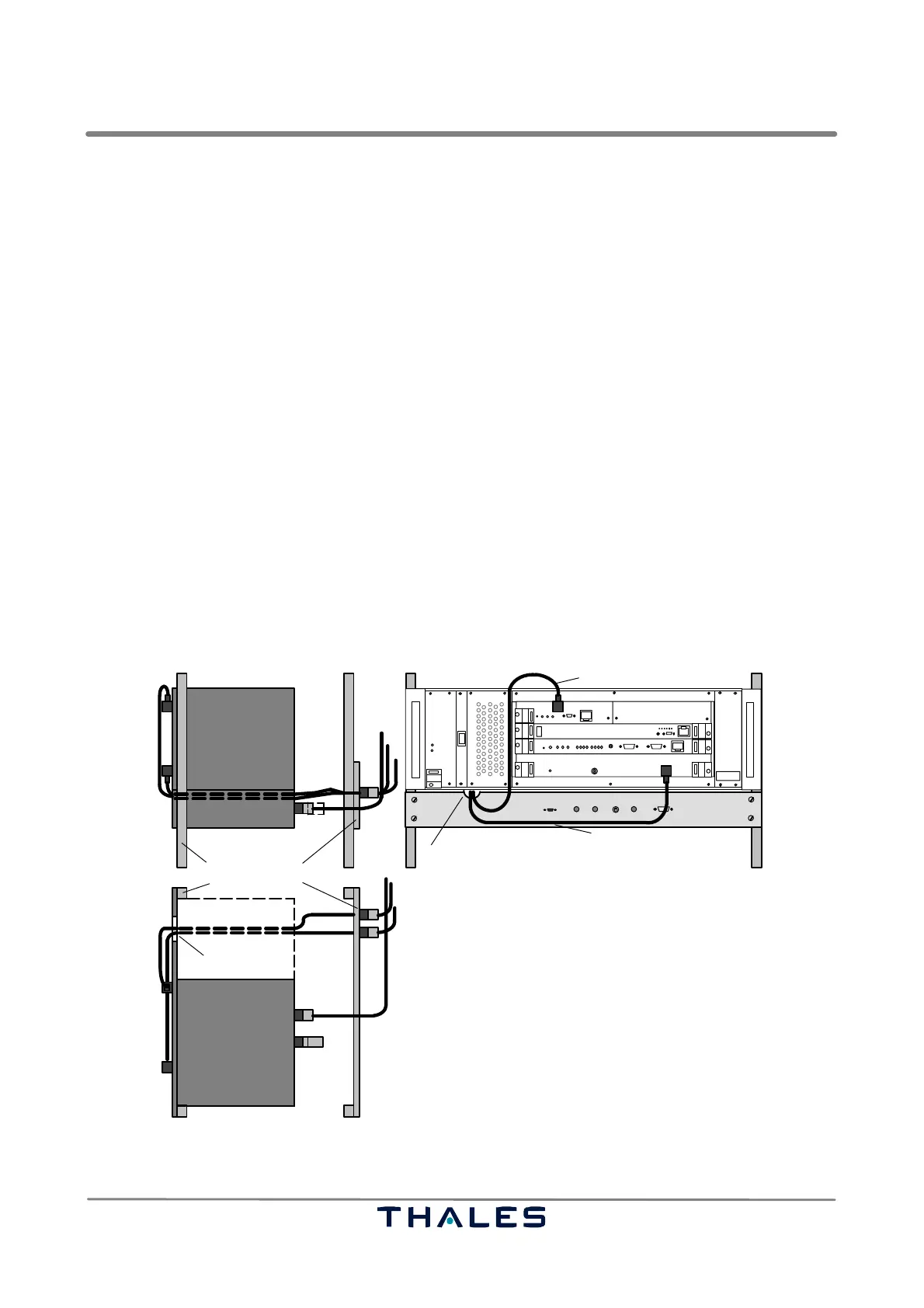
2.1.6 Rack Integration example of the AS680 Ground Station
Ground Stations and Site Monitors follow the 19" form factor for easy installation into existing racks.
The RF cables connecting the site equipment (Ground Station and Site Monitor) to the antennas are
usually placed at the rear of a 19" rack. While the Site Monitor has its RF connectors (N−type) right
at the rear, the RF input connectors (SMA) of the Ground Station are located on its front panels.
To relieve the more delicate SMA connectors of the Ground Station front from mechanical stress im-
posed by stiff RF cables, an Exchange Panel is supplied together with the appropriate cables. The
Site Monitor front panel has a recess to guide through these exchange cables from the rear to the
Ground Stations front. The whole configuration is shown in Fig. 2−16.
SM cable
SPU
I
0
THALES
THALES
GPS cable
ADS−B RX cable
SM
SPU
SM
Exchange Panel19" rack
50 ohms
load
RF OUT 1
RF OUT 2
GPS cable
ADS−B cable
SPU
SM
Top view
Side view, right hand rear
rear
front view
N/N
SMA/N
SMA/N
recess
recess
N/TNC
N/N
Fig. 2−16 Proposal of arrangement and cabling of SPU, SM and Exchange Panel in 19" rack