AS 680/682
Description, Operation and Maintenance Subsystem Description
ADS−B
2−1Ed. 10.07
CHAPTER 2
SUBSYSTEM DESCRIPTION
2.1 ADS−B GROUND STATION AS 680
2.1.1 General Description
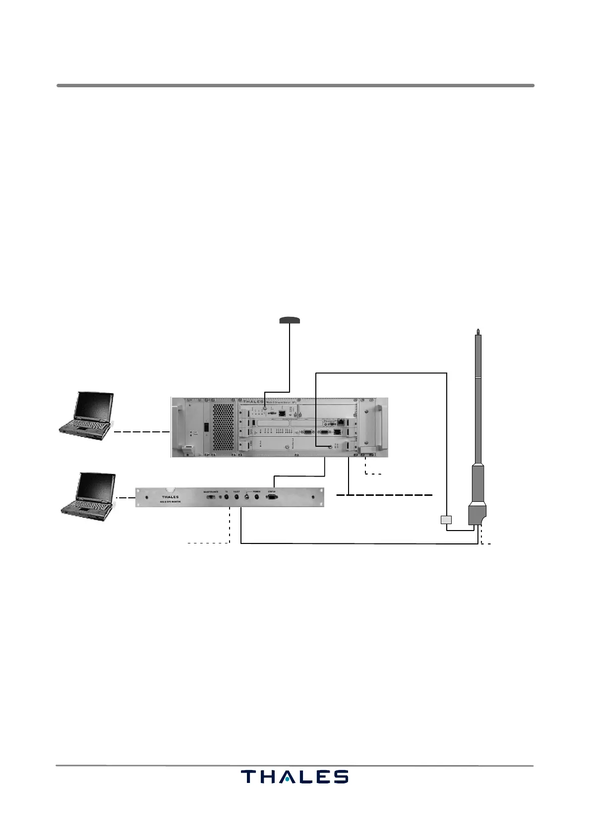
See Fig. 2−1.
The ADS−B Ground Station AS 680 developed by Thales is a compact and autonomous unit based
on 1090 MHz Extended Squitter (ES) reception. The main functions of AS 680 are to receive and pro-
cess ADS Broadcasts on 1090 MHz and to directly output decoded consistent target report data to
an ATC application using the international ASTERIX standard category 21, ed. 0.23. Further central
equipment is not needed. In order to output complete ASTERIX reports, data from different ADS−B
reports (extended squitter messages) of the same target are collected (e.g. position, velocity, etc.).
The Ground Station processing makes sure that data derived from different extended squitter types
are combined in a consistent way.
Signal Processing Unit (SPU)
GPS−antenna
AAU
ADS−B receiving antenna
and Low Noise Amplifier (LNA)
Site monitor (SM)
LCMS
Maintenance
Ethernet connection to ATC/RCMS
from GS B SM
BITE signal
RF cable, 1/2" cellflex,
Local Monitoring
up to 30 m
RF cable, 1/2" cellflex, up to 2 m
RF cable, 1/4" cellflex, up to 30 m
Status exchange
to/from GS B (option)
RF cable, 1/4" cellflex
up to 10 m
(optional)*
*NOTE: Instead of this optional RF signal line from other Site Monitor the signal is received via RF.
to GS B antenna (optional)*
Fig. 2−1 AS 680 Ground Station equipment (example Ground Station A)
The AS 680 includes internal and external Built In Test Equipment (BITE) functionality, which allows
optimizing the automatic and manual failure detection and identification process. The status as well
as all functions and parameters of the Ground Station can be monitored and controlled via the simple
network management protocol (SNMP). An additional local serial connection to which a standard ter-
minal (e.g. a laptop PC) can be connected serves as console port to perform the basic setup or to
perform local maintenance and control. The basic system data interface is a 10/100BaseT Ethernet
port. On top of Ethernet, the following standard communication protocols are used:
− ASTERIX Category 021 on UDP/IP for operational ADS−B target reports
− SNMP on UDP/IP for remote configuration, maintenance, monitoring and control
− UDP/IP for raw data
− Secure Shell (SSH) for direct remote access on operating system level
− Secure Copy (SCP) for remote upload of configuration files and executables