AS 680/682
Description, Operation and Maintenance Subsystem Description
ADS−B
2−7Ed. 10.07
In addition to providing the absolute timing reference for the internal timing system (GTS), the receiver
also makes available the measured position of its GPS antenna as well as other data like various dilu-
tions of precision (DOP) and the satellites actually being tracked by the unit.
In case of the DG14 based GTS, an integrated receiver autonomous integrity monitoring (RAIM) func-
tionality allows to determine the horizontal level of protection (HPL) in the same way as an ADS−B
equipped aircraft. HPL indicates the ability to determine satellite errors within the current constella-
tion. It is used to provide position and time as base for the timing system.
The GPS signal is received through an L−band antenna and a low noise amplifier (integrated in the
antenna). The RF port also supplies power to the antenna.
The GTS module provides also the physical connector to the auxiliary Ethernet interface of the Ground
Station. The Local Control and Monitoring System (LCMS), consisting of a maintenance Laptop PC,
can be connected to that auxiliary Ethernet connector for control and maintenance purposes.
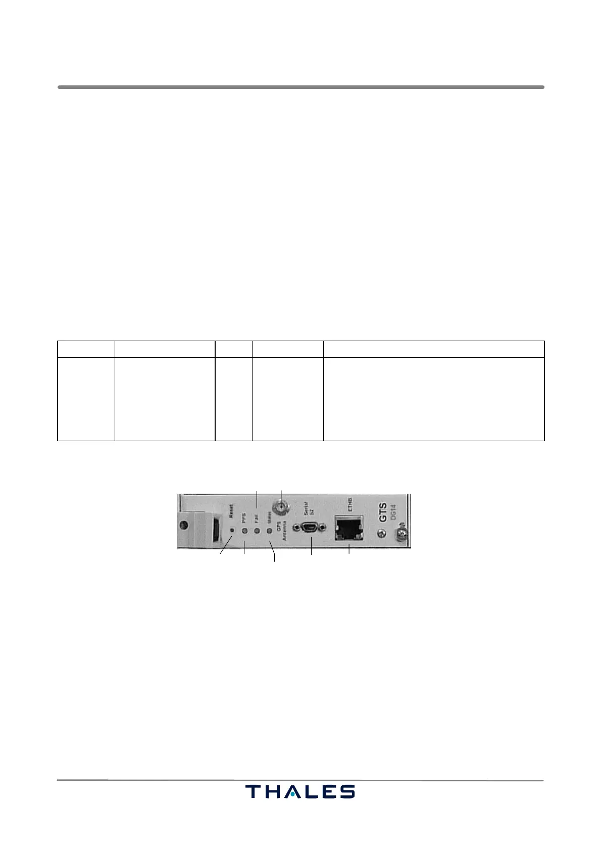
The following table gives a definition of the indicators and controls of the GTS module.
Board Indicator Color Control Function of control or indicator (lit or flashing)
GTS DG14
LED, Fail
LED, PPS
LED, Status, bicolor
red
green
red/
green
Reset Recessed key, manual reset of GPS board
Normally out; lit if RX function faulty.
Flashing once a sec., indicates a PPS trigger.
On, if satellites not locked;
Flashing once for each channel with a valid
satellite.
BITE RF in from antenna/DC out to antenna
Ethernet (auxiliary)Serial RS232Receiver reset
MicroSubD
Data Flow
Status
GTS module DG14
Fig. 2−9 GTS module/GPS receiver DG14