AS 680/682
Subsystem Description Description, Operation and Maintenance
ADS−B
2−6 Ed. 10.07
2.1.4.1 Receiver Unit (RXU)
See Fig. 2−8.
There are two versions: RXU1 and RXU2. The RXU2 with Ref. No. 83142 71503 replaces the RXU1
with Ref. No. 83142 71502. The actual improved RXU2 can operate without an AAU and needs no local
oscillator adjustment. The RXU1 operates only with a receiving antenna including the AAU.
The RXU receives the Mode S downlink RF signals from the antenna and prepares it as a video input
signal for the Signal Processing Board. The receiver provides a logarithmic receiving characteristic
so that the relation between RF input power and video signals is not linear. Optimal performance of
the RXU is achieved by an accurate local oscillator frequency (f
lo
=1030 MHz ±1 MHz). The Low Noise
Amplifier (LNA) within the AAU is supplied with DC via the antenna cable from the RXU. It is protected
against short circuit. The DC supply can be disabled on the RXU board (jumper X3) if no LNA (AAU)
available (see also section 7.3.8.1). If the the RXU is used without an AAU or other equipment is con-
nected to it, jumper X3 of the RXU needs to be removed. In addition, there is no band−pass filter at
the input of the SPU/RXU. If the RXU subassembly should be operated without AAU, a separate dedi-
cated 1090 MHz bandpass filter is needed at the input.
A monitor output delivers the ADS−B video signal for maintenance purposes. A digital storage oscil-
loscope with high impedance connected to this output interface supports adjusting the RXU perfor-
mance (see also sections 3.2.5 and section 3.2.6) and allows further analysis of the received signal.
An indicator "Fail" indicates a malfunction of the RF path (i.e. RXU, LNA, antenna and cabling) as re-
sult of BITE.
The following table gives a definition of the indicators and controls of the RXU.
Board Indicator Color Control Function of control or indicator (lit or flashing)
RXU LED, Fail red Normally out; lit if RX function is faulty.
RXU2 only LED, AAU green Lit if AAU supply is available.
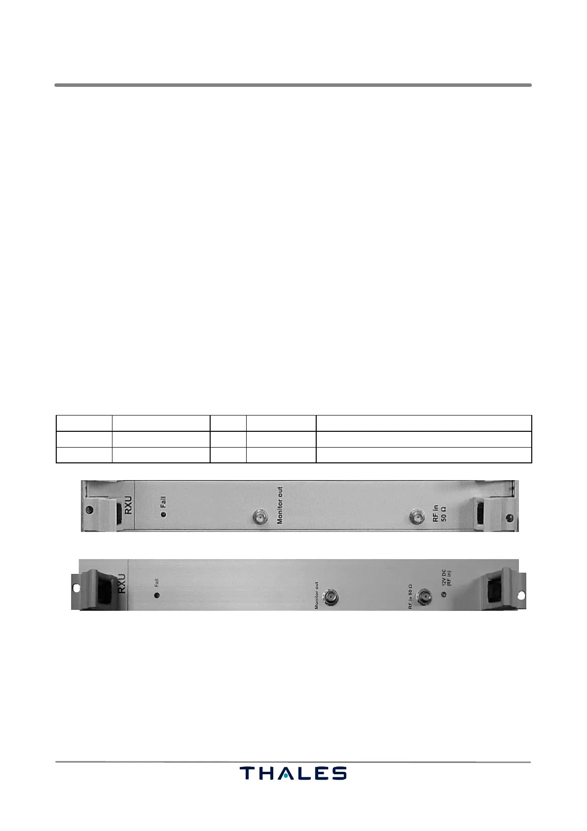
BITE LED Video Monitor out RF in from antenna/DC out to LNA
AAU supply indication
RXU1
RXU2
BITE LED Video Monitor out RF in from antenna/DC out to LNA
Fig. 2−8 RXU (RXU1 and RXU2), front view
2.1.4.2 GPS Timing System (GTS)
See Fig. 2−9.
The GTS DG14 GPS receiver (or optional the GTS B12) processes signals from the Global Positioning
System (GPS) and the geostationary satellites from satellite based augmentation systems (SBAS).
It uses 14 discrete parallel channels for Coarse/Acquisition (C/A) code−phase (pseudo range) mea-
surements and carrier phase measurements on the GPS L1 band (1575.42 MHz).