AS 680/682
System Description Description, Operation and Maintenance
ADS−B
1−4 Ed. 10.07
The two Ground Stations A and B (or 1 and 2) comprise identical components (Fig. 1−2, 1−3), i.e.:
− Signal Processing Unit (SPU)
− Site Monitor (SM)
− GPS RX antenna
− ADS−B RX antenna
− Antenna Amplifier Unit (AAU)
− cables and accessories
In addition the Local Control and Monitoring System (LCMS) is used for local operation and/or local
maintenance purposes. It is built by a standard Laptop computer as data terminal including the ap-
propriate application software. It is similar to that of the RCMS excluding the MTSC application.
Two Remote Control and Monitoring Systems (RCMS 1 and 2) may be installed each centrally at the
Air Traffic Controller building (ATC) at two dedicated sites. The two RCMS 1 and 2 are built up with
identical components which comprise (Fig. 1−2):
− Personal Computer with dual TFT LCD−monitor; operating system: Linux
− Application Software including:
S Master Technical System Control (MTSC),
S Technical System Control (TSC),
S multiple network interfaces,
S raw data recording and replay tools, Asterix data recording/replay and conversion,
S ADS−B Display with a display configuration tool.
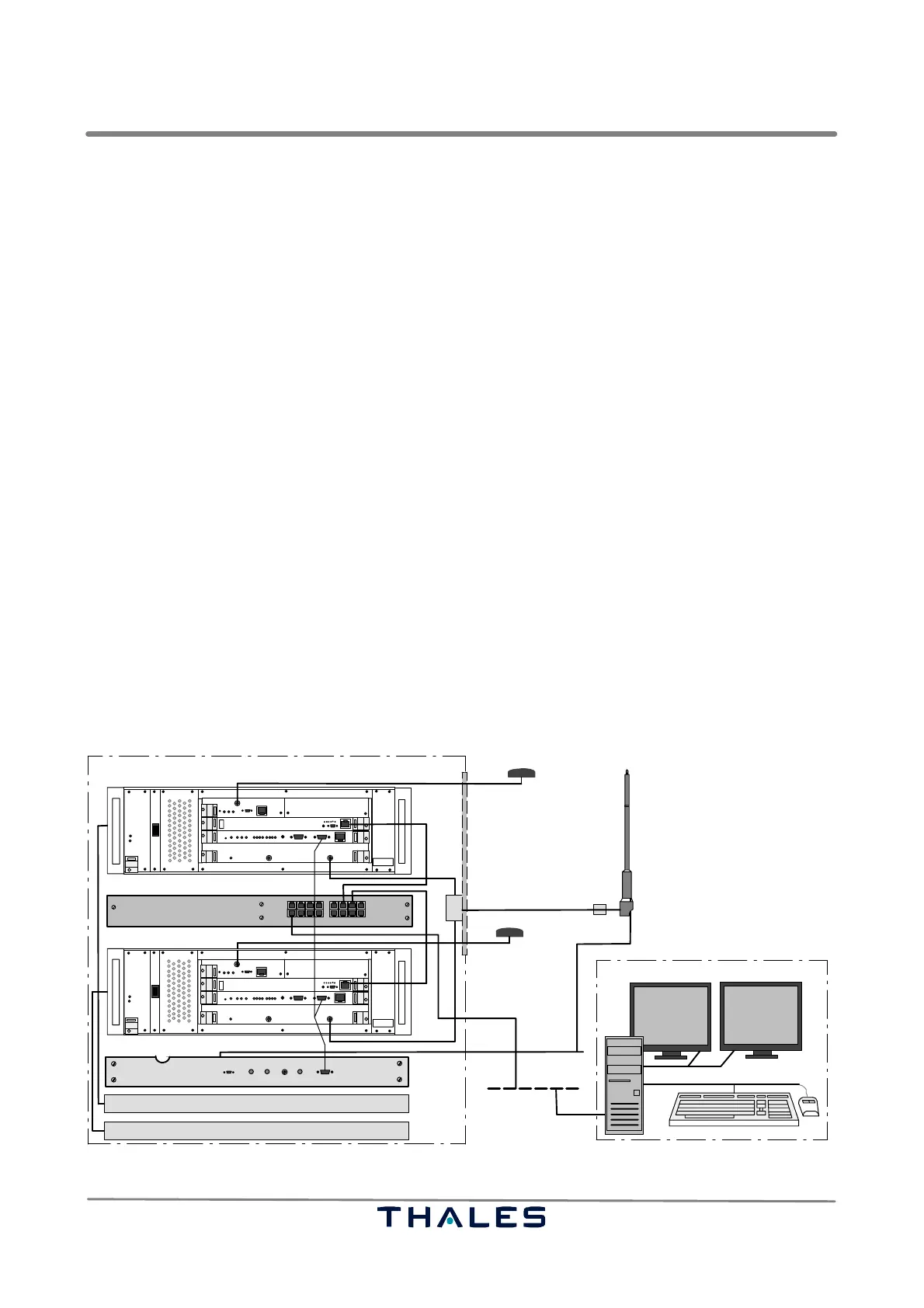
In addition there are some options which may be used according to customer requirements, e.g.:
− an Uninterruptable Power Supply system (UPS) which buffers the operation of the GS in case of
a mains power fail, used in the AS 682 version for each SPU (Fig. 1−3)
− a Data Switch, used in the AS 682 version for interconnection of each SPU, UPS to LAN (Fig. 1−3)
− an independent site monitor device which is not directly connected to the GS (e.g. other location)
but offers radiation of test signals via an individual antenna.
RCMS−configuration
ADS−B Ground Station AS682
GPS−antenna 1
THALES
I
0
THALES
I
0
Site Monitor
LAN
19" cabinet
SPU2
SPU1
AAU
RF
UPS1
UPS2
GPS−antenna 2
ADS−B RX antenna
RF distribution
Exchange Panel
Data switch
Fig. 1−3 ADS−B AS 682 in 19" cabinet, equipment overview, examplary configuration