AS 680/682
Description, Operation and Maintenance System Description
ADS−B
1−3Ed. 10.07
1.2 SYSTEM COMPONENTS
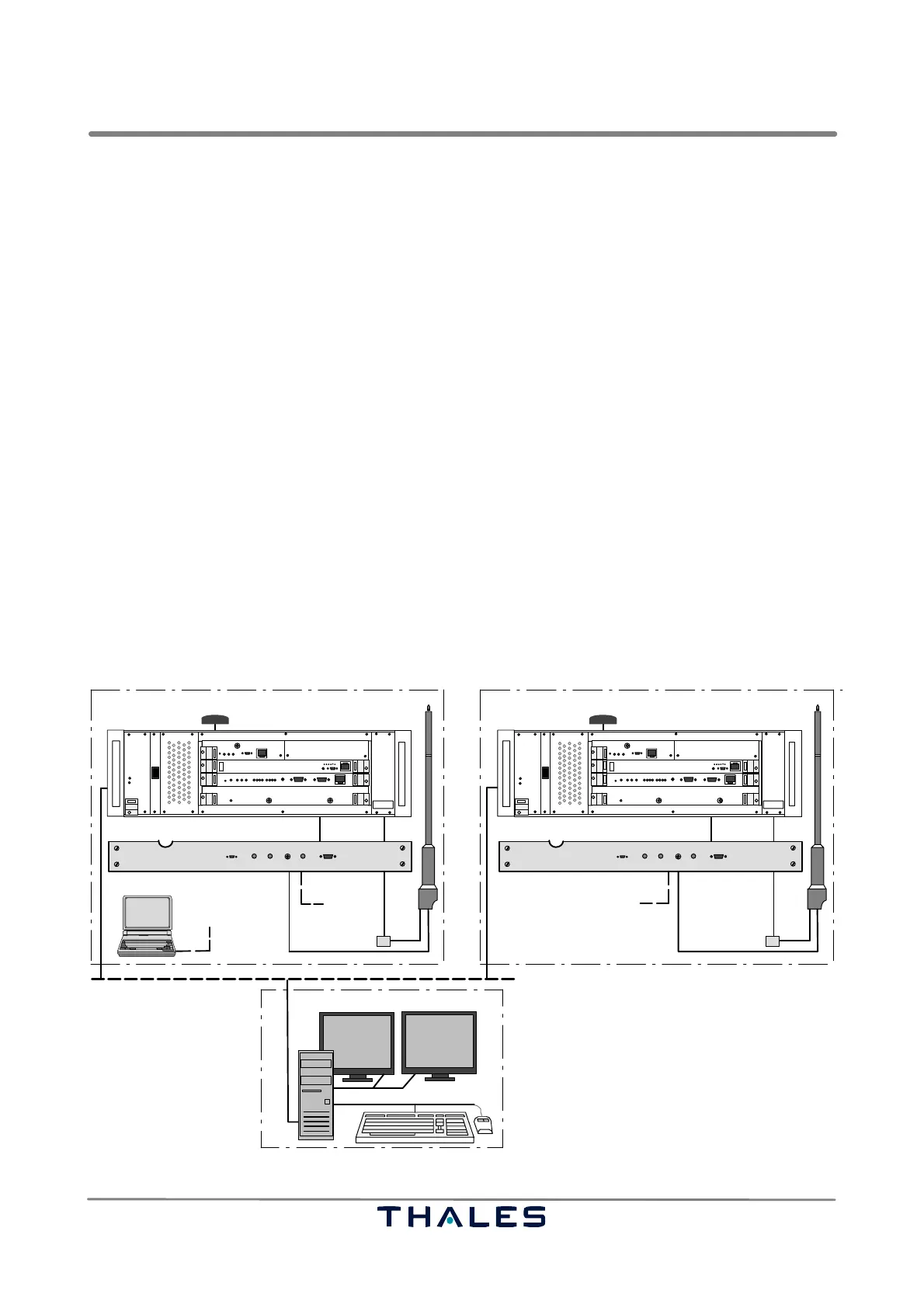
See Figs. 1−2, 1−3.
The ADS−B Ground Station AS 680 or AS 682 is a system that offers Automatic Dependent Surveil-
lance Broadcast (ADS−B) services based on the 1090 ES SSR Mode S data link (1090 MHz). The
AS 680 version builts a single system for integration in an existing environment, while the AS 682 ver-
sion builts a completely wired and redundant system including uninterruptible power supplies (UPS)
assembled in a 19" cabinet. The ADS−B Ground Station receives Mode S ADS−B Broadcasts (ex-
tended squitters) periodically emitted by equipped aircraft. These messages contain information
about the aircraft’s current position, altitude, velocity vector, callsign, etc. The Ground Station pro-
vides the decoded data as standard ASTERIX output via an attached network to Air Traffic Control
surveillance applications. The signal processing techniques applied within AS 680 allow for reliable
operation even under heavy radio load conditions and long−range coverage. The usual application
is en−route surveillance with coverage ranges of up to 250 NM. Other applications are terminal area
surveillance and airport surface surveillance. The system consists of 3 main subsystems:
− AS 680/682
The ADS−B Ground Stations subsystem to be installed at remote sites.
− RCMS
The centralized Remote Control and Monitoring System (RCMS), to monitor, configure and control
the ADS−B Ground Station.
− Maintenance equipment
LCMS (Local Control and Monitoring System: Laptop), extender card and a set of spare parts
Two ADS−B Ground Station subsystems (GS A and GS B) are usually installed at one remote site.
The subsystems are supplied by either optional mains voltage (100 to 240 VAC) or standard DC volt-
age (nominal 24 VDC). The DC voltage may be generated by Solar powered DC generators.
RCMS−configuration
LAN
ADS−B Ground−Station A
GPS−antenna ADS−B receiving antenna
AAU
Site Monitor
ADS−B Ground−Station B
GPS−antenna ADS−B receiving antenna
Site Monitor
to antenna GS Ato antenna GS B
SPU
SPU
THALES
I
0
THALES
THALES THALES
local connection
Station 1 or 2
optional optional
I
0
RX B
LCMS
AAU
RX A
Fig. 1−2 ADS−B AS 680, basic equipment configuration, examplary overview