AS 680/682
Description, Operation and Maintenance Subsystem Description
ADS−B
2−5Ed. 10.07
SPU part number/
serial number label
Chassis part number/
serial number label
Power consumption/
supply data label
Input voltage 18−36 VDC
Current in 4.5 A max.
Fuses 2x 6.3 AT/250 V
1/4" x 1.1/4"
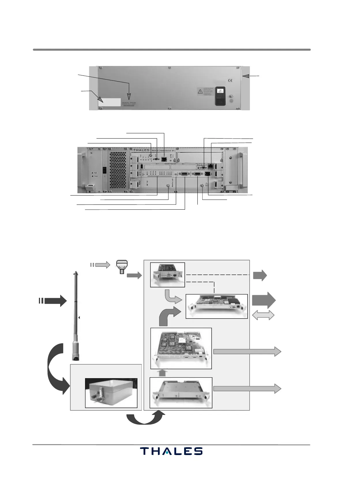
Fig. 2−5 SPU location of part/serial numbers
SBC serial port, V.24 (5)
GPS antenna RF input (4)
GPS subassembly, serial port
GPS subassembly, auxiliary Ethernet port (6)
Main Ethernet port (7)
Site Monitor BITE status and/or door lock switch etc.(9)
RF input from AAU, ADS−B antenna (3)
TX control, not used (10)
BITE status I/O (8)
NOTE: Reference numbers in brackets () correspond to Fig. 2−2 .
Video signal monitor output (11)
Activity indicators
Trigger in, not used
Fig. 2−6 AS 680 Interfaces, overview
The AS 680 information flow as well as the various intermediated states of processing that AS 680
provides and the diagnostic interface are shown in Fig. 2−7.
GPS signals (RF)
RF signals
GPS data
Raw data
Video signal
SPB
RXU
GTS SPU
SBC
ADS−B signals (RF)
AAU
Remote access (SNMP)
Improved RF signals
Video signal monitor output
Raw data
SNMP
Main
Aux.
ADS−B antenna GPS antenna
RF signals
Asterix CAT 21
through
Ethernet interf.
through
Ethernet interf.
through
Ethernet interf.
through
Ethernet interf.
through
RF connector
Fig. 2−7 AS 680 information flow, overview