AS 680/682
Description, Operation and Maintenance Subsystem Description
ADS−B
2−3Ed. 10.07
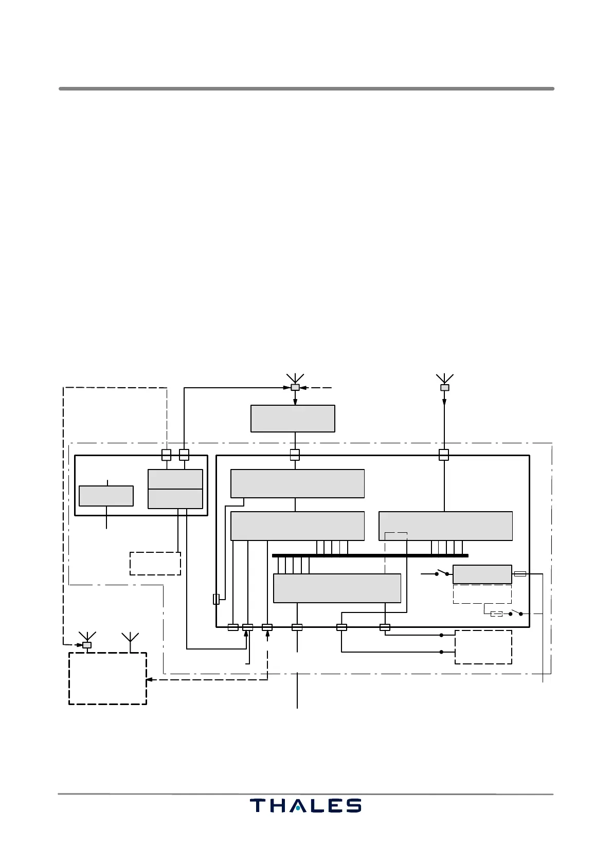
The Ground Station communication interfaces are:
− Ethernet 10/100Base−T main interface, Fig. 2−2/7
− separate Ethernet 10Base−T auxiliary interface, e.g. for maintenance purposes, Fig. 2−2/6
− console port V.24 for local set up, Fig. 2−2/5
Other interfaces are:
− an external BITE I/O to accommodate BITE status summary from another (redundant) Ground Sta-
tion, Fig. 2−2/8
− an external sensor input to connect site monitor BITE status, door lock switches, smoke detectors,
etc., Fig. 2−2/9
− a telegram generator output (not used in this application) to drive a Mode S interrogator transmitter
and Mode S downlink transmitter, e.g. as an ADS−B test generator or for TIS−B transmissions,
Fig. 2−2/10.
NOTE: The I/O port of the SPB has only operational insulation and must only connect to Safety
Extra Low Voltage (SELV) as defined in IEC 60950. Connecting other than SELV circuits
can create hazards.
Receiver Unit
RXU
Signal Processing Board
SPB
GPS Timing System
Single Board Computer
GTS
SBC
Power Supply
F1
AC/DC option*
S1
S2
100 to 240 VAC (optional)
DC out
RF Filter
Low−noise Amplifier
AAU incl.
VME−bus
ADS−B
Generator
Power Supply
Interface
SPU
Site Monitor
Ethernet
Ground−Station B
Ground−Station A
1
Ethernet
0
to ATC center/RCMS
local configuration
interface (V.24)
DC in nom. 24 V
Site Monitor BITE status
door lock switches etc.
local configuration
interface (V.24)
operational data (Asterix Category 021)
maintenance data (SNMP)
GPS RX antenna
local maintenance
interface (Ethernet)
BITE status I/O
Monitor signal of
2nd independent
Ground Station
Maintenance
Laptop
Maintenance
Laptop
LCMS
or nom. 24 VDC (18 to 36 VDC)
VHF GPS
F1=2x 6.3AT DC
F1=2x 0.8AT AC
DC/DC
F1
(SPU+SM)
DC/DC
from GS 2/SM
(20 to 28 V)
Fuses:
* AC/DC converter can be used instead of DC/DC converter
ADS−B RX antenna (1090 ES)
optional**
optional
optional**
** Instead of this optional RF signal line from other Site Monitor the signal is received per RF.
1) 2) 3) 4)
5)6)7)8)9)10)
11)
TX control
Video
output
out
monitor
Fig. 2−2 ADS−B Ground Station AS 680 architecture (at one site)