AS 680/682
Subsystem Description Description, Operation and Maintenance
ADS−B
2−12 Ed. 10.07
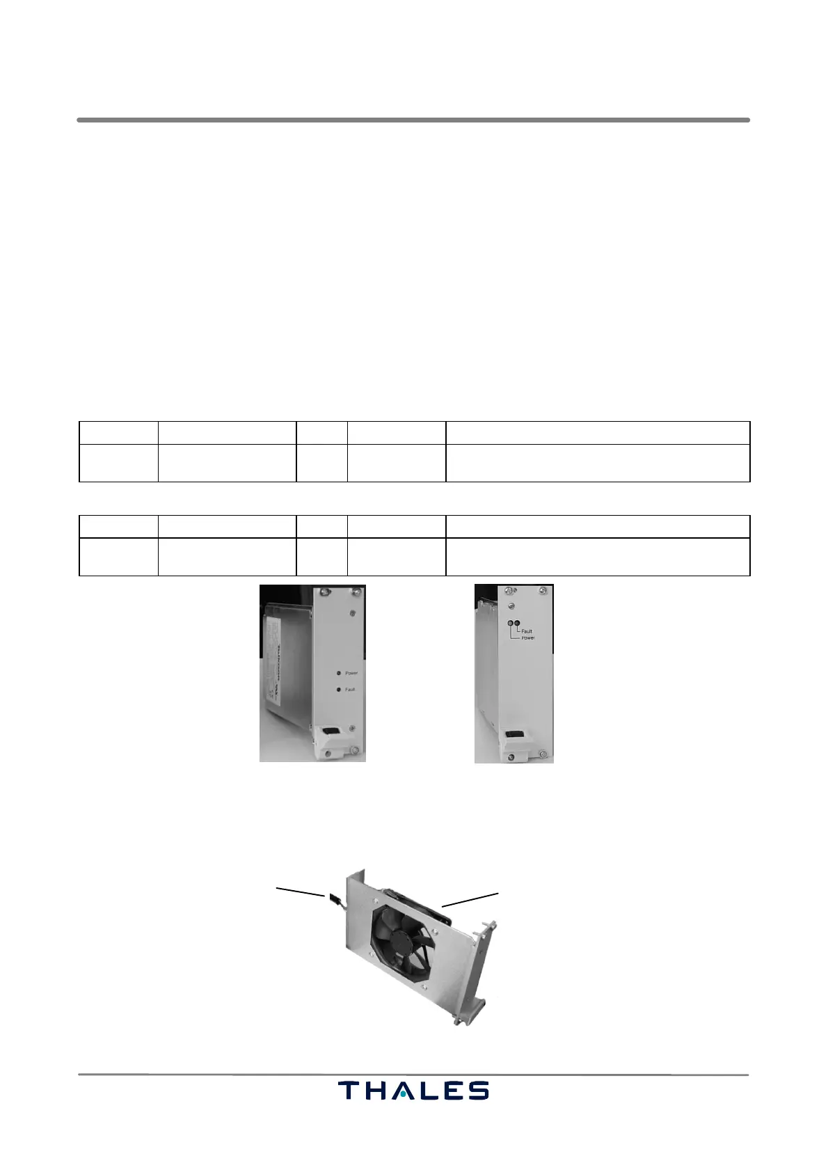
2.1.4.5 Power Supply
See Figs. 2−4, 2−12.
Power supply of the SPU can be performed with a DC supply of nom. +24 V or an AC supply of 100
to 240 VAC from mains. For this purpose two converters are available including associated connector
assembly (located at the rear of the SPU). The connector assembly contains the appropriate input
filter and fuses (see Fig. 2−4). The SPU is normally switched on or off with the DC switch (I/0) at the
front of the SPU. The converters deliver the following supply voltages:
− DC/DC converter (make Telkoor):
input 18 to 36 V/15 A max.; output +5V/25 A, +3.3 V/ 36 A, +12 V/3 A, −12 V/0.5 A
− AC/DC converter (make Schroff):
input 100 to 240 V/4 A max.; output +5V/40 A, +3.3 V/ 40 A, +12 V/5.5 A, −12 V/2 A
The following table gives a definition of the indicators and controls of the power supply modules.
Board Indicator Color Control Function of control or indicator (lit or flashing)
AC/DC or
DC/DC
LED, Fault
LED Power
red
green
Normally off; if lit, converter is faulty.
Normally on, DC input voltage available.
Power connector assembly (see Fig. 2−4):
AC/DC Mains Switch Switches AC/DC converter to mains (I/0)
Fuses DC
AC
2x T6.3H, protects DC input supply line.
2x T0.8H, 250 V, protects AC input supply line.
DC/DC converter AC/DC converter (option)
Fig. 2−12 SPU power supply options: DC/DC converter and AC/DC converter
2.1.4.6 Fan Unit
The fan unit is used to cool the internal subassemblies of the SPU. It is extractable for easy exchange.
Connector DC Fan (92 mm)
Fig. 2−13 Fan unit tray