AS 680/682
Description, Operation and Maintenance Subsystem Description
ADS−B
2−13Ed. 10.07
2.1.5 Site Monitor (SM)
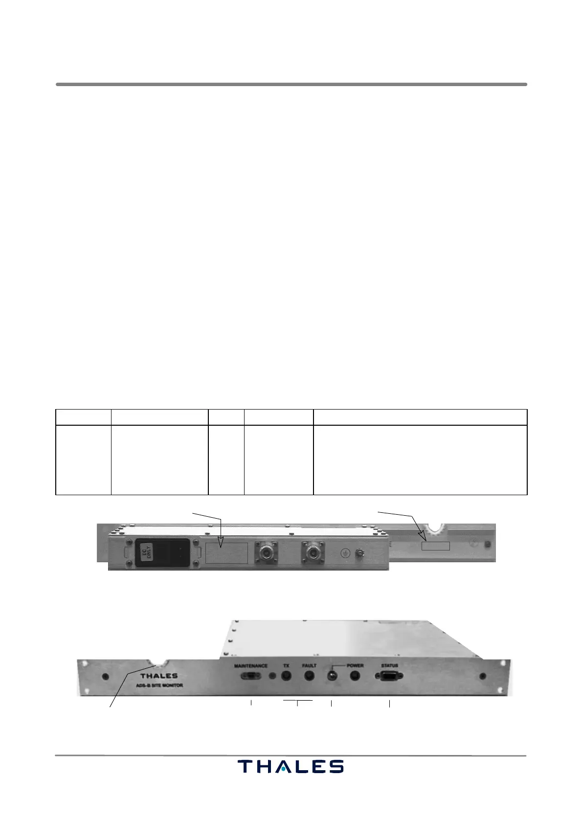
See Figs. 2−14, 2−15.
The Site Monitor is normally associated to a Ground Station (GS). It is intended to allow verification
of correct GS operation independent of environmental conditions. To achieve this, the Site Monitor
injects its fixed test message directly into the ADS−B antenna monitor probe. Determining the re-
ceived signal level, the Ground Station is thus able to verify if antenna, LNA and cables are working
within their specification. The Site Monitor of one Ground Station (e.g. GS A) can inject directly this
message both to the antenna of GS A (RF OUT1) and optionally GS B (RF OUT2) for testing on site.
If not in use, the RF outputs have to be terminated with 50 ohms. In usual configurations, only one
of the two outputs are used. The second output must therefore be terminated with the 50 ohms
dummy load supplied.
In the standard configuration, Ground Station GS B receives the Site Monitor A signal via mutual an-
tenna coupling.
The Ground Station also checks for correct data contents and correct timing of site monitor message.
Periodically, the Ground Station generates an Asterix test target report triggered by a configurable
set of conditions, e.g. if the site monitor signal is received properly and no BITE failure exists. The test
target message contains the site monitor address, but the Ground Station GPS position and figure
of merit. An ATC application using ADS−B is thus able to determine whether a Ground Station is op-
erational or not based on received operational data. After power up, the Site Monitor will indicate a
fault for about 60 s while transmission activity starts immediately.
The following table gives a definition of the indicators and controls of the Site Monitor.
Board Indicator Color Control Function of control or indicator (lit or flashing)
SM LED, TX
LED, FAULT
LED, POWER
green
red
green
DC switch
Flashing, if telegram is sent.
Normally out; lit, if SM function is faulty.
DC power on/off
Lit, if power available and DC switch to on.
DC input 24 VDC nom; incl. fuses RF OUT1 RF OUT2 PE
SM part number/serial number label
Power consumption/supply data label
Fig. 2−14 ADS−B Site Monitor (SM), rear view, connectors and identification labels
LED indicationsSerial V.24 Status outDC switch
MicroSubD
SubD
cutout for RF cable pass through
Fig. 2−15 ADS−B Site Monitor (SM)



 To Next Page