AS 680/682
Installation and Setup Description, Operation and Maintenance
ADS−B
3−16 Ed. 10.07
3.2.4 Switch On Ground Station
a) DC/DC version used: Switch on local main DC supply.
AC/DC version used: Set AC switch at backpanel of all SPU to on ("I")).
b) Set DC switches at front panel of all SPU and SM to on ("I"). The systems start. The initialisation
procedure takes some time while LED "Fail" of SPB of the SPU is lit, others are on or slow flashing.
Finally all LED of the SPB are checked, before the system is ready for operation. No fault indication
should be noted after the systems have start up.
c) To perform initial Ground Station and Site Monitor settings see section 3.2.7 and section 3.2.8.
NOTE: If a LCMS Laptop is used connect the LCMS Laptop to the serial interface MicroSubD con-
nector of the Ground Station respectively Site Monitor (or, for GS, the auxiliary Ethernet
connector of the SPU/GTS DG14) using the suitable interface cable (zero modem cable).
If the LCMS Laptop used does not include a serial interface connector but an USB port,
a special conversion cable (USB to Serial) has to be used. This cable is optional available.
Further setup of the application software and user roles are described in section 3.3. The basic prepa-
ration of the RCMS/LCMS and the installation of operating and application software is described in
in Chapter 8. After setup, a site verification test procedure and a related installation report form is given
in section 3.6.
3.2.5 Check and Adjustment of the GS Receiver Frequency (RXU)
The optimal performance of the Ground Station depends on the SPU/RXU local oscillator which is
factory adjusted to its intended frequency of 1030 MHz ±1 MHz. To ensure the performance, it is man-
datory to verify this frequency during installation. It is also recommended to perform this check as
preventive maintenance item every 2 years to ensure continuous performance of the SPU.
Perform for RXU1 (83142 71502) only: If necessary adjust frequency as described in section 7.1.7.1.
NOTE: The RXU2 (83142 71503) requires no adjustment of the local oscillator G1.
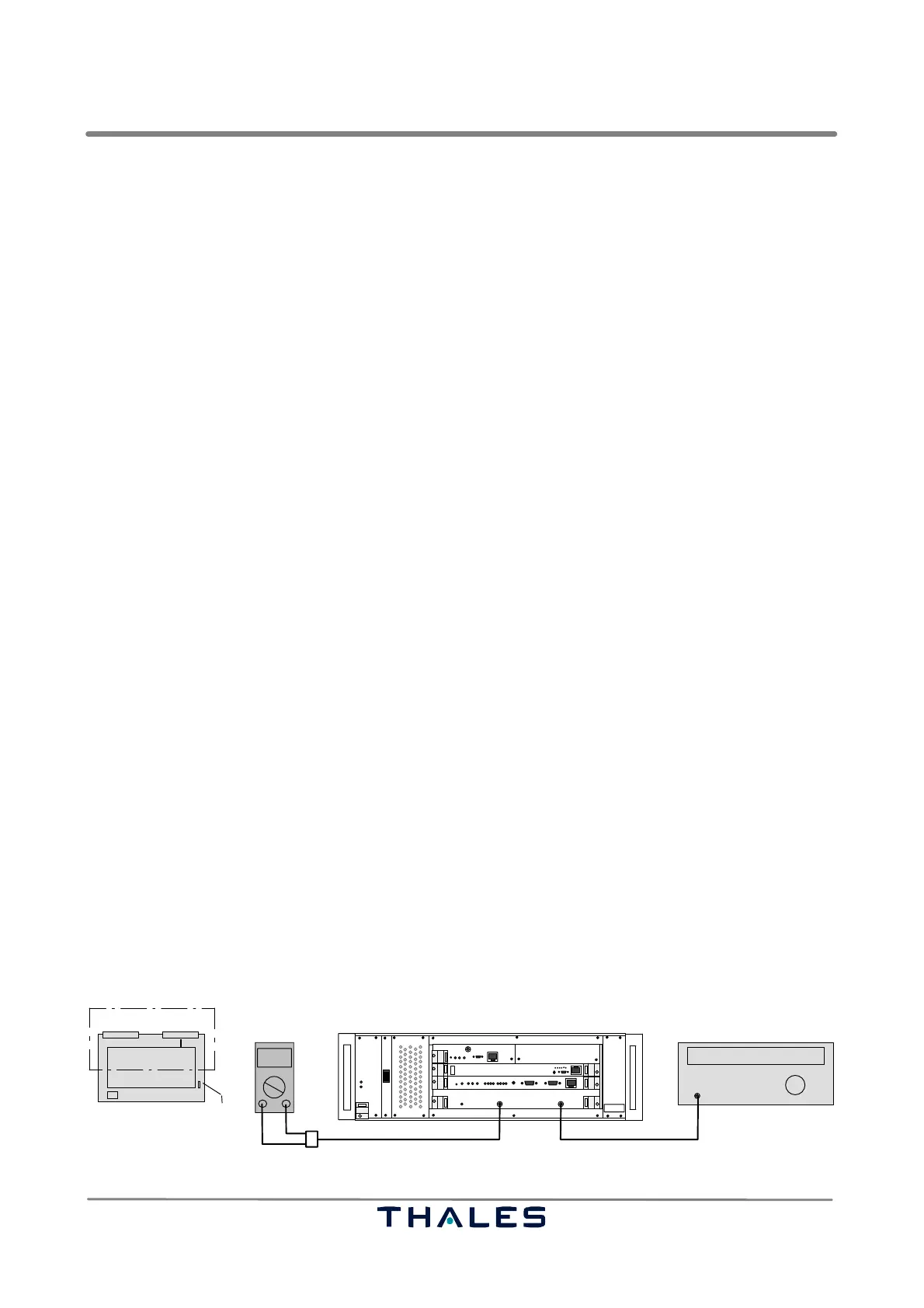
Perform the following procedure to check the frequency (refer to Fig. 3−16):
a) Switch off the correspondent SPU to be checked. Remove RF cable from SPU connector RF In.
b) Withdraw RXU board until jumper X3 (RXU1) or X1 (RXU2) is visible. Open X3 (RXU1) or X1 (RXU2).
Insert RXU board again.
c) Connect the RF Generator to connector RF In; connect Digital Voltmeter to connector Monitor Out.
d) Set RF Generator to apply an RF signal of 1090 MHz and P= −80 dBm to connector RF In.
e) Switch on the affected SPU.
f) Vary the RF frequency about ±3 MHz at the RF generator to get a maximum DC voltage reading
at the Digital Voltmeter. The maximum should be within 1089 to 1091 MHz. If not, an adjustment
of the local oscillator frequency (LO) on the RXU is required. Refer to section 7.1.7.1.
g) Switch off the affected SPU. Remove measuring cables. Withdraw RXU board. Set X3 (RXU1) or
X1 (RXU2) again. Insert RXU board and connect RF cable as normal again.
I
0
Monitor Out
1090 MHz
000.0
Digital voltmeter RF generator
RF In
Adapter cable SMA/BNC/Banana plug
SPU
Cable SMA/SMA or adapter SMA/BNC
SPU
RXU
X3 or X1
RXU partly withdrawn.
top view
RF out
Fig. 3−16 Test setup frequency check of local oscillator of RXU