AS 680/682
Description, Operation and Maintenance Installation and Setup
ADS−B
3−17Ed. 10.07
3.2.6 Adjustment of the SPU/RXU Receiver Sensitivity Level
The SPU/RXU forwards a video signal to the SPB. The SPB input stage is DC coupled. All signals
(noise) below 300 mV will be discarded. The video signal contains a noise floor. Noise level depends
on radio environment, used antenna and cable length. The RXU provides an adjustable DC offset us-
ing a DIP switch (refer to 7.3.8) to adapt the actual noise to the trigger level:
− Noise floor below 300 mV: reduce detection of small signals (far aircraft).
− Noise floor above 300 mV: produce false detections
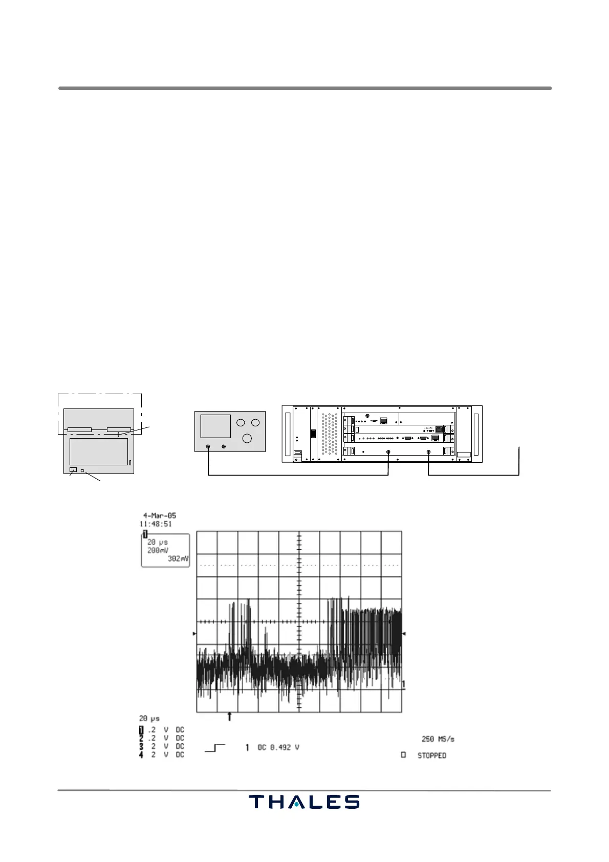
To adjust the SPU/RXU input sensitivity perform the following steps for each channel (Fig. 3−17):
a) Switch off the correspondent SPU to be checked.
b) Use of RXU1: Connect an oscilloscope to the monitor output of the RXU.
Use of RXU2: Connect an oscilloscope to the monitor output of the RXU. Jumper X2 is set to 1−2.
c) Switch on the affected SPU. Notice the noise value. If the level has to be adjusted:
− Switch off the correspondent SPU. Remove RF cable.
− Withdraw RXU. Set the DIP switch (refer to 7.3.8) to the convenient value (approx. 300 mV).
− Insert the RXU. Connect RF cable.
d) Switch on the affected SPU. Refer to the examples in Fig. 3−18 to 3−20 as adjustment help.
e) Repeat this operation until the required level is obtained. Switch off the affected SPU. Remove RF
cable and oscilloscope probe. Connect the RF antenna cable as normal. Switch on the affected
SPU for normal operation.
I
0
Monitor Out RF In
SPU
from ADS−B antenna
SPU
RXU
DipSwitch
RXU,
top view
maintenance adapter
Ch1 in
Oscilloscope
Probe RF cable
X2 (RXU2 only)
RXU1 only
optionally plugged on
Fig. 3−17 Test setup sensitivity level adjustment of RXU
Signal at monitor output (1)
Fig. 3−18 Receiver sensitivity level setting, signal at monitor output (1 of 3)