AS 680/682
Subsystem Description Description, Operation and Maintenance
ADS−B
2−18 Ed. 10.07
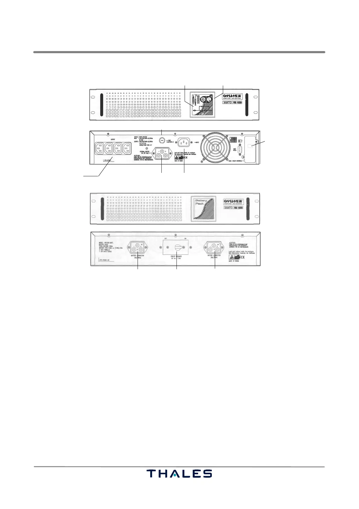
Mains out Mains inInterconnection
to extension
Fuse
Indication panel (LED) On and Stdby button
rear view
front view
rear view
front view
Interconnection
to base unit
Interconnection
to extension 2, not used
and network connector
additional SNMP board
Security switch
Extension pack
Base unit
Fig. 2−21 Uninterruptible Power Supply
− LINE−LED
The green LINE−LED lights up if mains voltage is applied to the UPS input.
LINE−LED blinks when the phase and neutral conductor have been reversed at the input of the
UPS system.
If LINE−LED and BATTERY−LED light up, the mains power supply is out of tolerance.
− BATTERY−LED
The orange−coloured BATTERY−LED lights up when the mains power supply has failed and the
inverter is being powered by the batteries.
− BYPASS−LED
The orange−coloured BYPASS−LED lights up when the UPS system is supplying voltage pro-
vided by the mains power supply system via the bypass.
− INVERTER−LED
The green INVERTER−LED lights up if the inverter is operating and powering the UPS output.
− FAULT−LED
The red FAULT−LED lights up and an acoustic warning signal is issued every second when the
UPS system is overloaded.
The red FAULT LED lights up and an acoustic warning signal is issued when the UPS system
is in fault condition. Press the Standby−button in order to turn off the warning tone.