7-5
User Manual PN 84469 Rev B
Connector Location
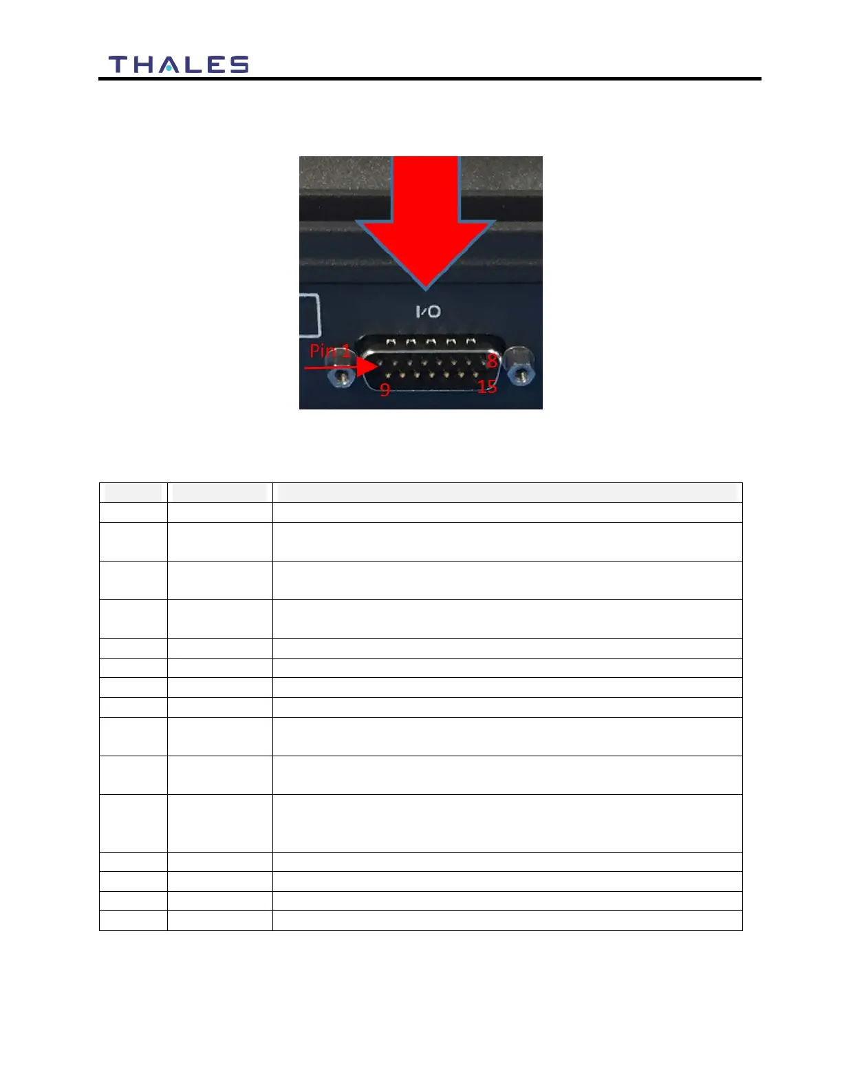
The DB-15 connector with Pin out shown in Figure 7-2.
Figure 7-2 GPIO Connector Pin Detail
Table 7-2 GPIO Connector Pin Definition
Radio Gateway functionality, differential (+) Hi-Z Audio Input from
external Radio
Radio Gateway functionality, Differential (+) Low-Z Audio Output
to external radio (mic input)
Radio Gateway functionality, Radio initiated voice into terminal
(optional)
SOS remote functionality, Ground pin to activate internal SOS
Software configurable GPIO pin #1 (future)
Radio Gateway functionality, differential (-) Hi-Z Audio Input from
external Radio
Radio Gateway functionality, Differential (-) Low-Z Audio Output
to external radio (mic input)
Radio Gateway functionality, Output PTT from terminal to external
radio, short to ground for PTT enabled, Open drain requires external
Software configurable GPIO pin #2 (future)


 To Next Page