7-3
User Manual PN 84469 Rev B
CONNECTOR DETAILS
General Purpose Inputs / Outputs (GPIO)
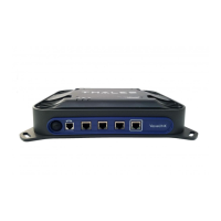
Refer to Figure 7-2 for the connector and its pinout. The connector is located on the back of the
BDU and is labeled I/O. The GPIO has 4 main functions. Some of the functions are reserved for
this connector are not yet implemented (they are reserved for future use.) Refer to Table 7-2 for
the pin descriptions of the GPIO connector.
1. 1-Wire SOS/Distress This is activated when Pin 5 has been connected to GND signal
(ANY of the pins 1, 8 or 12) for more than 3 seconds.
Once set, it sends an automated message stating SOS has been triggered. This message
contains Latitude, Longitude, Altitude and predefined user message (setup in
management portal) to a message recipient.
IF Location Services are turned on, it will increase frequency of transmission to
every 10 seconds.
NOTE: THERE IS NO LOCAL INDICATION OF DISTRESS BEING SENT
This security feature is for user protection. The ONLY way to remove active Distress is
to enter Management Portal under DISTRESS TAB


 To Next Page