CUTMASTER A60
SERVICE 5-16 Manual 0-4982
C. Input Capacitor PCB Test
1. Using an ohmmeter check continuity between the
following points:
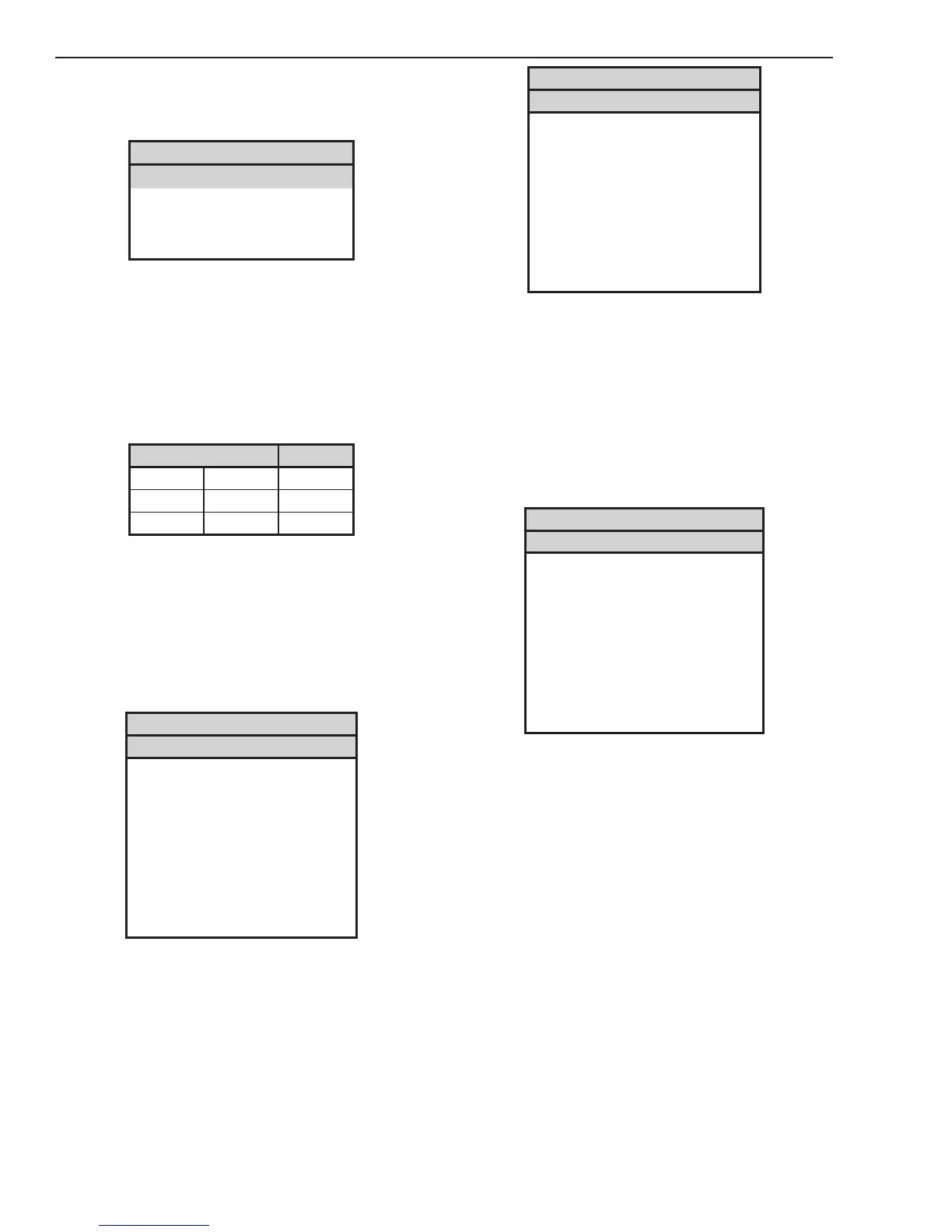
Input Capacitors
Meter + Meter - Indication
MTH 2 MTH 4 Charging
MTH 4 MTH 5 Open
MTH 6 MTH 5 Charging
Most meters will show a charging action. Initially a
low resistance will be shown and then the resistance
will start to increase. If the meter probes are reversed
the reading will decrease to zero, then start charging
in the opposite polarity.
2. If a short is found replace Capacitor PCB assem-
bly.
3. Check continuity between the following points
Input relays Indication
MTH 2 MTH 6 Open
MTH 4 MTH 6 Open
MTH 4 MTH 5 Open
4. If a short is found, replace Capacitor PCB assem-
bly
D. IGBT Modules Test
1. Disconnect transformer wires from Main PCB
terminals PRI 1 (A) and PRI 4 (D).
2. Using an ohmmeter perform the following
checks
IGBT A
Meter (+) Meter (-) Indication
PRI 1 (A) MTH 2 ForwardBias
PRI 1 (A) MTH 4 Reverse Bias
MTH 2 PRI 1 (A) Reverse Bias
MTH 4 PRI 1 (A) ForwardBias
PRI 2 (B) MTH 2 ForwardBias
PRI 2 (B) MTH 4 Reverse Bias
MTH 2 PRI 2 (B) Reverse Bias
MTH 4 PRI 2 (B) ForwardBias
IGBT B
Meter (+) Meter (-) Indication
PRI 3 (C) MTH 6 ForwardBias
PRI 3 (C) MTH 5 Reverse Bias
MTH 6 PRI 3 (C) Reverse Bias
MTH 5 PRI 3 (C) ForwardBias
PRI 4 (D) MTH 6 ForwardBias
PRI 4 (D) MTH 5 Reverse Bias
MTH 6 PRI 4 (D) Reverse Bias
MTH 5 PRI 4 (D) ForwardBias
3. If the test reveals a failed component, replace
Main PCB and perform main contactor test – Sec-
tion 5.11-A. If no problem is found, reconnect the
transformer wires to Main PCB.
E. Output Diode Module Test
1. Disconnect transformer wires from Main PCB
terminal SEC 1.
2. Using an ohmmeter perform the tests in the
chart
Output Diode Module
Meter (+) Meter (-) Indication
SEC 1 WORK1 ForwardBias
SEC 1 CHOKE1 Reverse Bias
WORK1 SEC 1 Reverse Bias
CHOKE1 SEC 1 ForwardBias
SEC 2 WORK1 ForwardBias
SEC2 CHOKE1 Reverse Bias
WORK1 SEC2 Reverse Bias
CHOKE1 SEC 2 ForwardBias
3. If the test reveals a failed component, replace
Main PCB. If no problem is found, reconnect the
transformer wires to Main PCB.
F. Pilot IGBT Test
1. Disconnect wire from Main PCB terminal TIP1
2. Measure continuity on Main PCB between test
point GND1 to terminal TIP1
3. If the test reveals a failed component, replace
Main PCB. If no problem is found, reconnect wire
to Main PCB.
Signal Information
Many of the signal listed will be low voltage signals
that will be in one of two states: +12VDC (High) or
0VDC (Low) with respect to PCB common. When a
signal name is preceded by the “/” mark, it denotes
that the signal is an active low. For example:
/OVERTEMP – This signal is normally High but
when an over temperature fault exists, this line will
change state to a Low.

 Loading...


