CUTMASTER A60
Manual 0-4982 5-9 SERVICE
4. There are three (3) ARC VOLTs signals available
from the J6 connector.
a) J2-9 (+) to J2-7 (-)
b) J2-5 (+) to J2-6 (-) (Auto Interface PCB J3 con-
nector with jumper installed between pins 1
and 2) = ARC VOLTS divided by 50
c) J2-5 (+) to J2-6 (-) (Auto Interface PCB J3 con-
nector with jumper installed between pins 2
and 3) = ARC VOLTS divided by 16
Measure the voltage between these points while pi-
loting (Open Circuit Voltage) and while cutting. The
voltages should approx as listed below
Open Circuit Voltage Cutting Voltage
a) 300 VDC 100 VDC
b) 6 VDC 2 VDC
c) 19 VDC 6 VDC
This completes the CNC Interface Test. If the above are
all correct then the unit is functioning correctly. If the
unit does not function as stated, then note the symptom
and proceed to Section "5.10, CNC Interface Problems".
5.07 Main Input and Internal Power
Problems
A. Primary input line fuse blows as soon as
primary disconnect is closed.
1. Primary input cable installed incorrectly.
a) Check wiring of primary power cable to the
contactor. See illustration below.
2. W1 jumpers installed incorrectly
a) Check jumper installation for correct phase
being used.
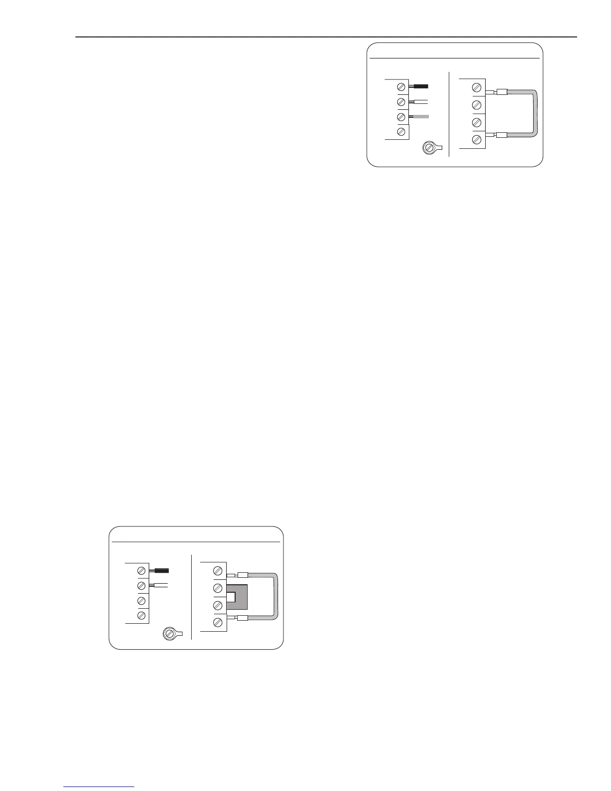
Art # A-07984_AB
Single-Phase (1ø) and Jumper Settings
L1
L2
L3
L4
Jumper L1 -L4
Jumper
L2-L3
L1
L2
L3
GND
L4
Single Phase Input Power Wiring
Art # A-07983_AB
Three-Phase (3ø) and Jumper Settings
L1
L2
L3
L4
Jumper L1 -L4
L1
L2
L3
GND
L4
Store copper jumper in spare parts box
Three Phase Input Power Wiring
3. W1 contactor points are stuck closed
a) Check per section 5.11-A
4. Primary plug not wired correctly.
a) Check manufacturer's plug installation in-
structions.
5. Primary input cable is defective.
a) Check cable for shorts.
B. Primary line fuses blow immediately after
ON/OFF SWITCH (SW1) is turned to ON
position.
1. Shorted Input Diode Module
a) Check per section 5.11-B
2. Shorted Input Capacitor PCB
a) Check per section 5.11-C
C. Gas flows with ON/OFF SWITCH in OFF
position
1. Foreign debris has lodged in gas solenoid.
a) Replace gas solenoid. This is a problem caused
by improperly filtered air supply. Customer
needs to add filtration to air supply prior to
unit inlet.

 Loading...


