CUTMASTER A60
SERVICE 5-6 Manual 0-4982
5.06 Circuit Fault Isolation
WARNING
The following procedures should not be at-
tempted by anyone who has not had proper
training or authorized to do so.
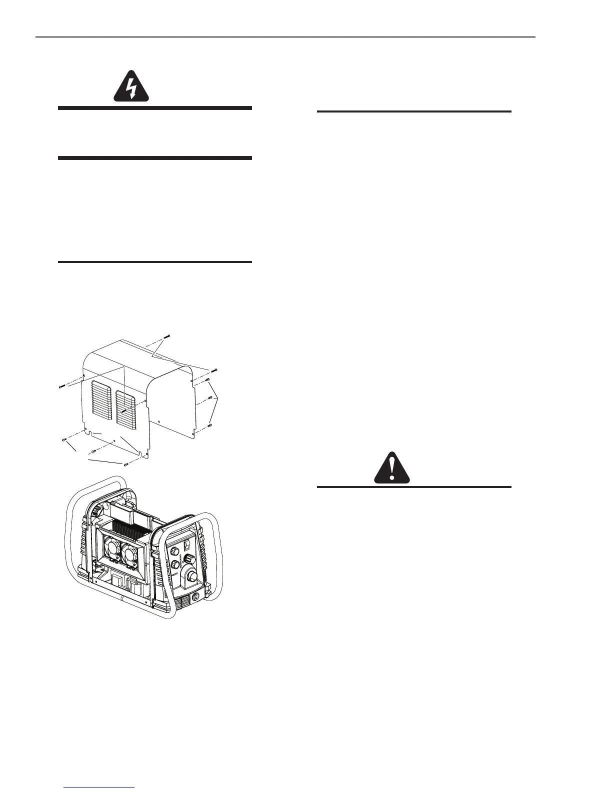
A. Cover Removal
1. Remove the NOTE screws which secure the cover
to the main assembly. Do not loosen the lower
screws inside the cut out slots in the bottom of
the cover.
NOTE
The upper screws and lower screws are not the
same. Do not mix them. The upper screws are
for threading into the plastic of the front and
rear panels. DO NOT use the finer threaded
lower screws for this.
Upper
Screws
Lower
Screws
Lower
Screws
Art # A-07947
Slots
2. Carefully pull the Cover up and away from the
unit.
B. Cover Installation
1. Reverse previous procedures for cover installa-
tion.
NOTE
When installing the upper screws, attempt to
reuse the original threads. The easiest way
to do this is by turning the screw counter-
clockwise until you feel the threads line up,
then begin to turn the screw clockwise to
tighten to 15-18 in. lbs. Do not over tighten.
C. Pre Power Up Tests
Prior to applying primary line power to the unit,
perform the following checks to prevent component
failure or blowing primary fuses. The troubleshoot-
ing guide will assume these tests were done and no
failure was found or that any failures found were
corrected.
1. Main Contactor (W1) Check – Section 5.11-A
2. Input Diode Module Test – Section 5.11-B
3. Input Capacitor PCB Test –Section 5.11-C
4. IGBT Modules Test – Section 5.11-D
5. Output Diode Module Test – Section 5.11-E
6. Pilot IGBT Test – Section 5.11-F
If all of the Pre Power-Up Tests are OK, proceed with
the trouble shooting guide.
CAUTION
Due to the close proximity of the Main PCB
to the Capacitor PCB, It is recommended to
use an insulated meter probe when making
measurements on the J2 connector on the
Main PCB. Do not short between the pins. Do
not short to the Capacitor PCB connections.

 Loading...


