CUTMASTER A60
Manual 0-4982 5-15 SERVICE
5.10 CNC Interface Problems
A. Nothing happens when jumper is installed
between J2-3 to J2-4.
1. Defective Automation Interface PCB (PCB 4)
a) Measure voltage on PCB 4 between J1-6 to J1-8
for 12VDC.
If 12VDC is present replace PCB 4
2. Defective Main PCB
a) Measure voltage on Main PCB between J1-6
to J1-8 for less than 2VDC.
If voltage is less than 2VDC, replace PCB 1
B. No OK-TO-MOVE signal while cutting.
1. Defective Main PCB (PCB 1)
a) Measure voltage on PCB 4 between J1-1 to J1-3
for 12VDC while cutting.
If 12VDC is present, replace PCB 1
2. Defective Automation Interface PCB (PCB 4)
a) Measure voltage on PCB 4 between J1-1 to J1-3
for less than 2VDC while cutting.
If voltage is less than 2VDC, replace PCB 4.
C. ARC VOLTS signals are low or not present
1. Defective Automation Interface PCB (PCB 4)
a) Replace PCB 4
5.11 Test Procedures
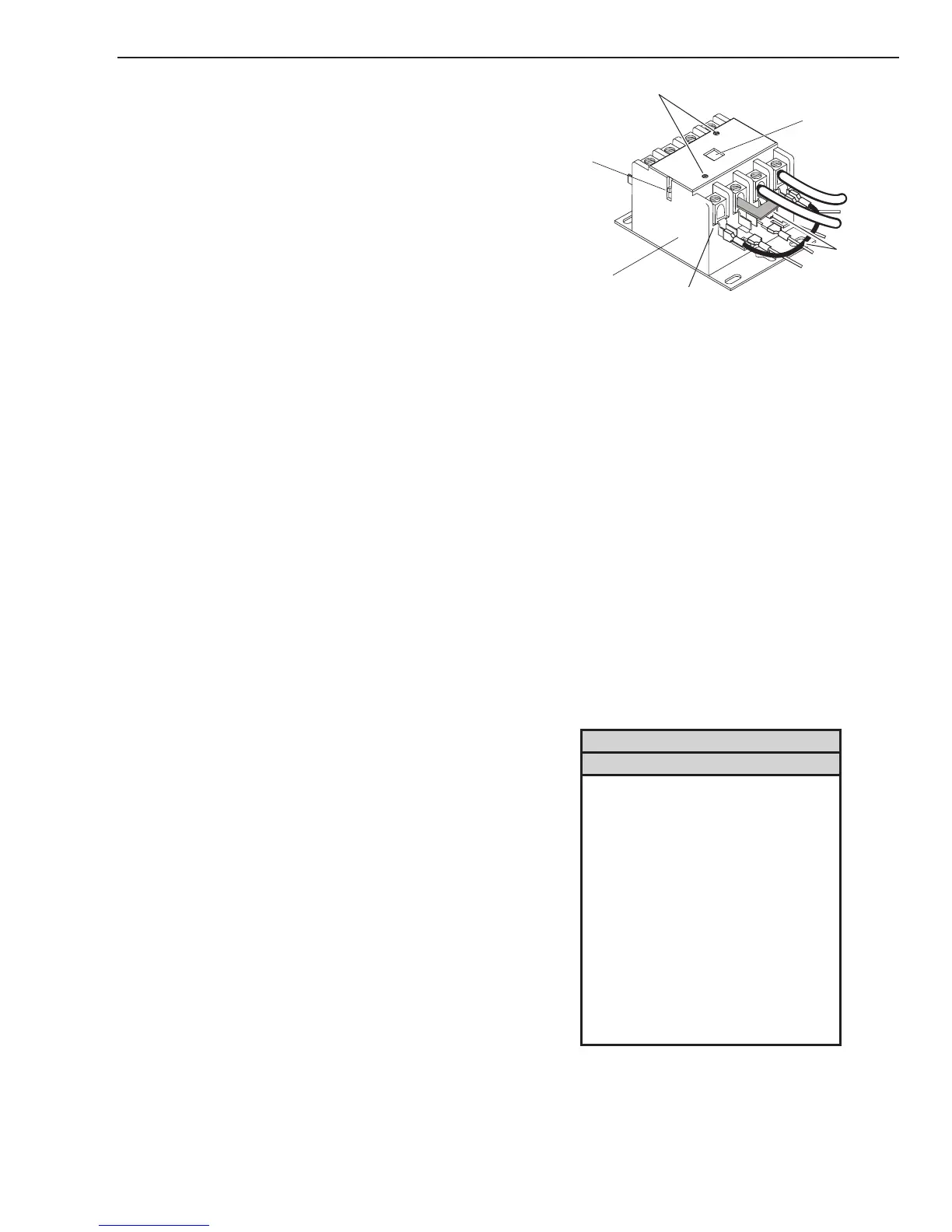
A. Main Contactor (W1) Test
1. Check continuity between:
L1 to T1
L2 to T2
L3 to T3
L4 to T4
The contacts should be open – no continuity.
L4 L3 L2 L1
T4 T3 T2 T1
Actuator Arm
Cover Screws
Input
W1 contactor wired for 1PH
Main Contactor
2. Retest continuity between terminals while engag-
ing the contacts manually. This can be done by
pushing down on the recessed actuator button on
the top of W1 or pushing down on the actuator
arm on the side of W1.
L1 to T1
L2 to T2
L3 to T3
L4 to T4
The contacts should be closed – Continuity
3. Visually check W1 contact points. To take the
cover OFF, remove the two cover screws shown
in the previous illustration. Replace if contacts
are stuck together or show excessive arcing
B. Input Diode Module Test
1. Using an ohmmeter perform the tests in the
chart
Input Diode Module
Meter (+) Meter (-) Indication
AC1 MTH 2 ForwardBias
AC2 MTH 2 ForwardBias
AC3 MTH 2 ForwardBias
MTH 2 AC1 Reverse Bias
MTH 2 AC2 Reverse Bias
MTH 2 AC3 Reverse Bias
MTH 5 AC1 ForwardBias
MTH 5 AC2 ForwardBias
MTH 5 AC3 ForwardBias
AC1 MTH 5 Reverse Bias
AC2 MTH 5 Reverse Bias
AC3 MTH 5 Reverse Bias
2. If the test reveals a failed component, replace
Main PCB and perform main contactor test – Sec-
tion 5.11-A

 Loading...


