CUTMASTER A60
Manual 0-4982 5-3 SERVICE
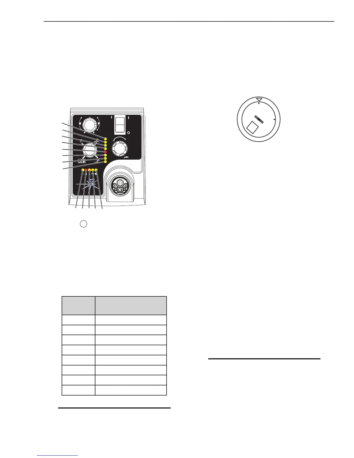
5.04 Fault Indicator
At initial power up, two lights will temporarily illu-
minate for 2-3 seconds to show the version of software
used.
To determine the first digit, count the function indicators
left to right, 1 through 5. To determine the second digit
count the pressure indicators, reading from bottom to
top, 0 through 7. In the example below the Temp indica-
tor and 75 psi indicators are on indicating the version
would be 2.3.
A
+
PSI BAR
MAXMAX
MINMIN
!
1
2
3
4
Art# A-07988
MIN
MAX
0
1
2
3
4
5
6
7
5
When the
"Fault" indicator is ON or blinking it
will be accompanied by one of the pressure indica-
tor lights depending on what the Fault is. Only one
of these faults will be displayed at one time. If more
than one fault exists, when the first fault is corrected
and cleared, the next fault will then be displayed. It
is possible to have a fault indicated in the function
indicators and another fault indicated in the pres-
sure indicators. The following table shows each of
the Faults possible.
Pressure
Indicator
Fault
Max Over Pressure
90 Internal Error
85 Shorted Torch
80 Consumables Missing
75 Start Error
70 Parts in Place
65 Input Power
Min Under Pressure
NOTE
Fault explanations are covered in the follow-
ing tables.
Explanation of Faults
" UNDER PRESSURE: Indicates that operating pres-
sure is set too low and power supply output
power will be disabled.
INPUT POWER: Indicates primary line voltage is
outside the operating limits of the power supply
as selected by the setting of INPUT VOLTAGE
SELECTION SWITCH at the rear of the unit. Low
is 208/230 VAC and high is 460 VAC.
S
LO
HI
Art # A-08316
PART IN PLACE: Indicates that the shield cup is not
properly installed or tightened.
START ERROR: Indicates that the START SIGNAL
was active (ie. Torch Trigger depressed, hand
held pendant switch on or CNC signal for torch
on) during one of three conditions:
1) During initial power up when ON/OFF
switch is turned to ON position
2) When fault which had been disabling the
system is cleared.
3) When the FUNCTION CONTROL SWITCH
Mode is moved from SET position to any of
the other three (3) modes of operation.
CONSUMABLES MISSING: Indicates that the elec-
trode, start cartridge or tip is missing or exces-
sively worn.
SHORTED TORCH: Indicates the torch or lead has
a shorted condition between positive and nega-
tive leads.
INTERNAL ERROR: Indicates a microprocessor error.
OVER PRESSURE: Indicates that operating pressure
is set too high. The Error Indicator will not flash
when the pressure is above 95 PSI. This LED will
remain on and the system will operate but pilot
starting and cut performance may be affected.
NOTE
The cooling fans will turn ON as soon as the
unit is turned ON. After the unit is idle for ten
(10) minutes the fans will turn OFF. The fans
will come back on as soon as the torch switch
(Start Signal) is activated or if the unit is turned
OFF, then turned ON again. If an over tempera-
ture condition occurs, the fans will continue to
run while the condition exists and for a ten (10)
minute period once the condition is cleared.

 Loading...


