CUTMASTER A60
Manual 0-4982 6-7 PARTS LIST
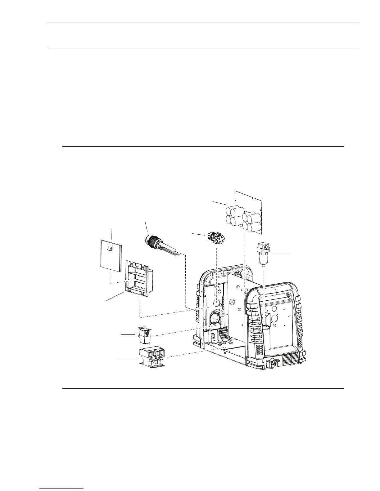
6.09 Right Side Replacement Parts
Item # Qty Description Ref Catalog #
1 1 Contactor, 4 Pole 9-8587
2 1 Solenoid, 12V 9-0114
3 1 Spare Parts Box 7-3267
4 1 Spare Parts Box Cover 7-3266
5 1 Console Quick Disconnect 9-0161
6 1 Regulator, with knob and mounting nut 9-0115*
7 1 Assembly, PCB, Input Capacitors non 600V 9-0126
7 1 Assembly, PCB, Input Capacitors 600V Only 9-0163
8 1 Filter, Auto Drain 9-0116
Not Shown
1 CNC Harness 9-9385
NOTE
*9-0115 regulator, If the serial number of the power supply is prior to #05078755 then kit number 9-0201
will be needed to replace not only the regulator (9-0115) but the logic PCB as well. Another way to tell if
the kit is needed is to see if the regulator has a small diameter tube coming out of the bottom fitting. If
there is a transducer and wire harness instead of the tube, the kit is not needed.
1
2
3
5
6
7
Art # A-08121
4
8
NOTE
Illustration may vary slightly from unit.

 Loading...


