CUTMASTER A60
Manual 0-4982 5-7 SERVICE
D. Initial Set up Conditions
This section is to help isolate the defective circuit
before troubleshooting, identify symptoms, and test
the unit for proper operation. Follow the instructions
as given to identify the possible symptom(s) and the
defective circuit. After repairs are complete, run the
following tests again to verify that the unit is fully
operational.
1. Connect gas supply to rear of Power Supply.
2. Turn ON gas supply and set operating pressure
per pressure setting label on power supply.
3. Set the Power Supply controls as follows:
• ON/OFFSWITCHtoOFFposition
• TurnFUNCTIONCONTROLSWITCHtoSET
position
• CURRENTCONTROLPOTENTIOMETERto
MAXIMUM position, fully clockwise.
E. Main Input and Internal Power Test
1. Connect Primary Line power to the unit.
2. Turn the ON/OFF SWITCH ( SW1) to ON position
and observe the following:
• Softwareversionisdisplayed(Seesection5.04
Fault Indicators)
After approx. three (3) seconds
• InrushrelayonPCB1energizes,startingpre-
charging of working capacitors.
• W1energizes
• ACandGASIndicatorscomeON
• Gasows
• FansturnON
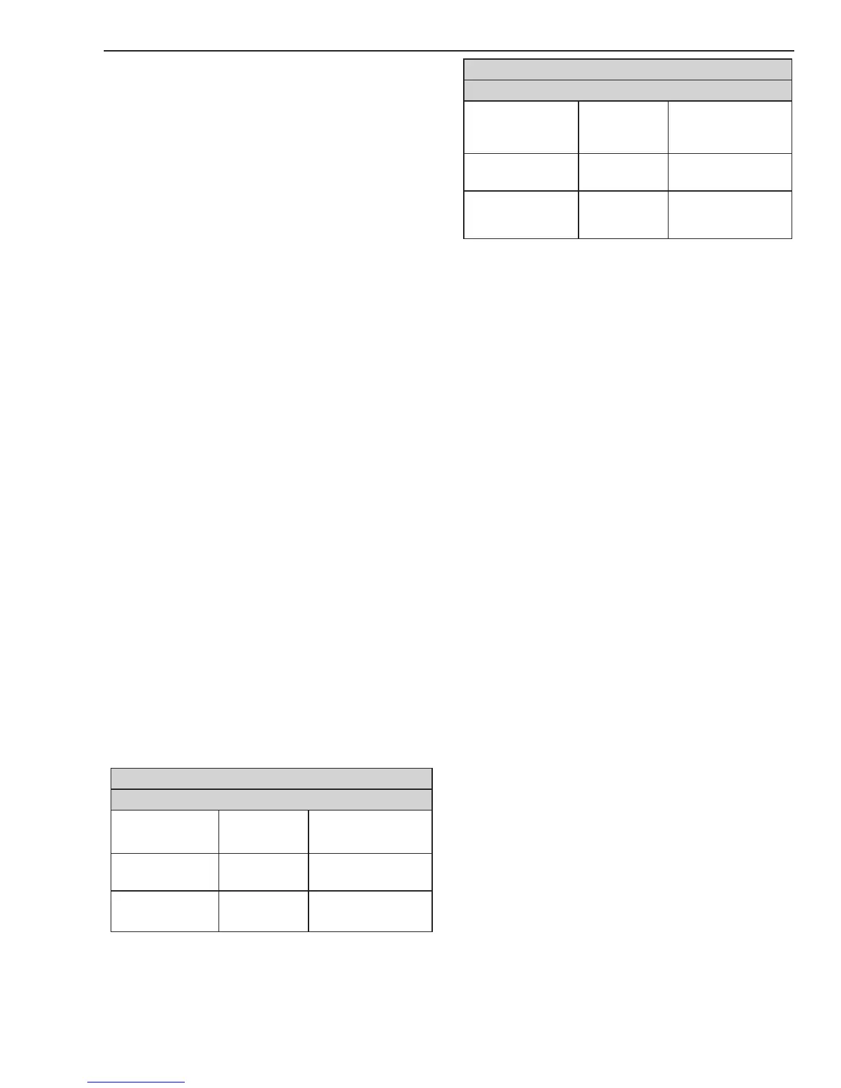
3. Adjust the pressure regulator to set the gas pres-
sure as specified in charts.
STANDOFF
CutMaster A-60 Gas Pressure Settings
Leads
Length
SL60
(Hand Torch)
SL100
(Mechanized Torch)
Up to 25'
(7.6 m)
75 psi
5.2 bar
70 psi
4.8 bar
Each additional
25' (7.6 m)
Add 5 psi
0.4 bar
Add 5 psi
0.4 bar
DRAG
CutMaster A-60 Gas Pressure Settings
Leads
Length
SL60
(Hand Torch)
SL100
(Mechanized Torch)
Up to 25'
(7.6 m)
80 psi
5.5 bar
75 psi
5.2 bar
Each additional
25' (7.6 m)
Add 5 psi
0.4 bar
Add 5 psi
0.4 bar
4. Turn FUNCTION CONTROL SWITCH to RUN
position
• SolenoidturnsOFF,gasstopsowing(pres-
sure display may increase slightly when gas
is not flowing)
This completes the Main Input and Internal Power Test.
If the above are all correct then proceed to the next section
"F. Pilot Arc Test". If the unit does not function as stated
above, then note the symptom and proceed to Section
"5.07, Main Input and Internal Power Problems".
F. Pilot Arc Test
1. Activate CNC Start signal, close Remote Pendant
switch or depress the Torch switch to establish a
pilot arc and note the following
• Gassolenoidopens
• Gasows
• Dependingontorchattached,afterasmuchas
two seconds the gas solenoid closes and gas
stops flowing momentarily, then gas solenoid
re-opens and gas resumes flowing
• DCLEDcomesON
• Pilotarcisestablished
2. Remove CNC start signal or release the Remote
Pendant or Torch switch
• Gascontinuestoow
• DCLEDgoesOFF
After 20 second post flow time
• Gassolenoidcloses
• Gasowstops
This completes the Pilot Arc Test. If the above are all
correct then proceed to the next section "G, Main Arc
and Controls Test". If the unit does not function as stated
above, then note the symptom and proceed to Section
"5.08, Pilot Arc Problems".

 Loading...


