cutmaster a60
Manual 0-4981 A-5 APPENDIX
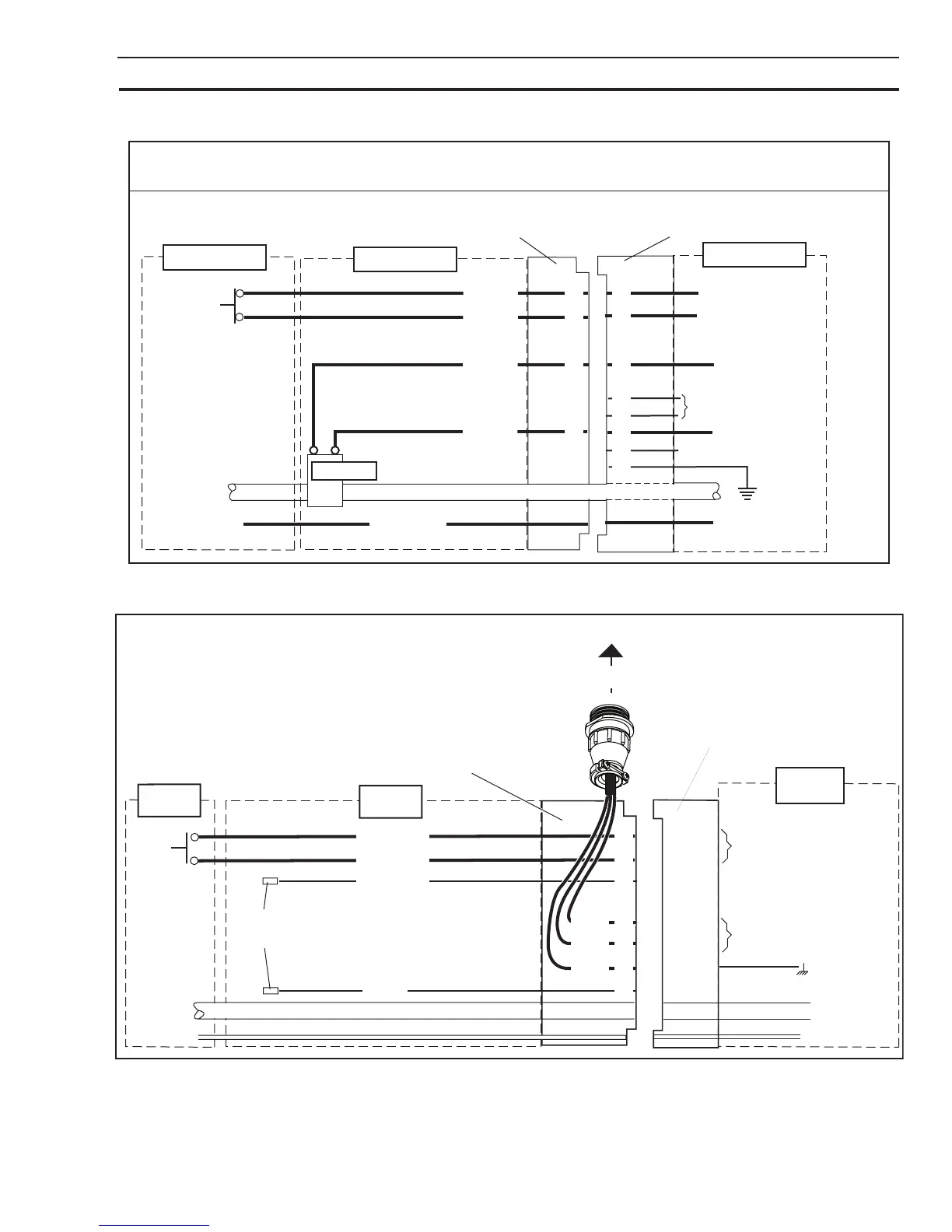
APPENDIX 4: TORCH CONNECTION DIAGRAMS
A. Automation (SL100SV) Torch Connection Diagram
Automated CutMaster Power Supply with ATC Torch Receptacle,
Automated SL100SV Torch (w/ Solenoid on Positioning Tube), Torch Lead with ATC Connector
Power Supply
PIP
Switch
ATC Male
Torch Leads Connector
ATC Female
Torch Receptacle
Negative / Plasma Lead
Pilot Lead
Art # A-07115
Pin No.s
Socket
No.s
1
2
5
4
3
7
6
8
Main PC Board
1
2
5
4
3
7
6
8
White
Black
Orange
Green
Main PC Board
Solenoid
Torch Leads
Torch Head
Not Connected
Not Connected
Main PC Board
Main PC Board
B. Machine (SL100) Torch Connection Diagram
Torch: Unshielded Mechanized SL100 Machine Torch
Leads: Leads with ATC Connector and
Remote Pendant Connector
Power Supply: with ATC Female Receptacle
Pilot
Negative / Plasma
Power
Supply
To Remote Control
Remote
Pendant
Connector
PIP
Switch
Not
Used
Male
ATC Leads
Connector
ATC Female
Receptacle
Pilot Lead
Negative / Plasma Lead
Torch
Leads
Torch
Head
Art # A-03798
1
2
5
6
4
3
8
7
To Power Supply
Circuitry
Green
To Power Supply
Circuitry
1
2
5
6
4
3
8
7
Black
White
Green
Black
Orange
White
This Page Intentionally Blank